Wireless time reference system and method

a time reference system and wireless technology, applied in direction finders, direction finders using radio waves, instruments, etc., can solve the problems of significant location errors, temperature changes in timing accuracy of internal clock circuits and concomitant positioning accuracy, and high cos

Active Publication Date: 2009-02-17
ZEBRA TECH CORP
View PDF5 Cites 57 Cited by
  • Summary
  • Abstract
  • Description
  • Claims
  • Application Information

AI Technical Summary

Benefits of technology

[0008]According to a first aspect of the invention, a system provides normalization of time (e.g., synchronizing or calibrating clocks, or providing an indication of skew compensation) of local clock circuits of plural spatially-located monitoring stations. One embodiment comprises a reference transmitter to transmit at least two RF pulses (UWB) that define a time reference interval wherein local clock circuits have respective detection circuits that detect and measure time durations of the time reference interval at respective receivers of the monitoring stations, and a processing device that determines a relationship (e.g., ratio) between time durations measured at receivers of at least two monitoring stations and that effects normalization of time (e.g., calibration) of local clock circuits according to the relationship. Once normalized, the local clock circuits may accurately measure times-of-arrival of subsequent object tag transmissions in an object location system. The processing device may effect normalization of time-of-arrival measurements among receivers of the monitoring stations by controlling the frequency of at least one local clock circuit of a monitoring station to maintain the relationship fixed (e.g., one-to-one) with respect to a frequency of a local clock of a selected other (i.e., master) monitoring station.

Problems solved by technology

Alternatively, where no wireline link is provided, prior untethered (i.e., wireless) systems utilized extremely accurate, albeit expensive, local timing references at each receiver but even then the timing accuracy of internal clock circuits and concomitant positioning accuracy is still subject to temperature changes, frequency drift or clock skew (which necessitated periodic synchronizing with a common source.
A disadvantage of Anderson's technique is that, if relatively inexpensive internal clocks are used as suggested, updates from the reference tag must be received at a sufficiently fast rate or clock drift between receivers (e.g., due to a simple frequency offset) will create significant location errors.
In essence, Anderson “pins” the epoch time of a tag transmission event for all receivers after a single calibration, but does not compensate for time-of-arrival drift due to clock frequency offsets.

Method used


Image

  • Wireless time reference system and method
  • Wireless time reference system and method
  • Wireless time reference system and method

Examples


Embodiment Construction

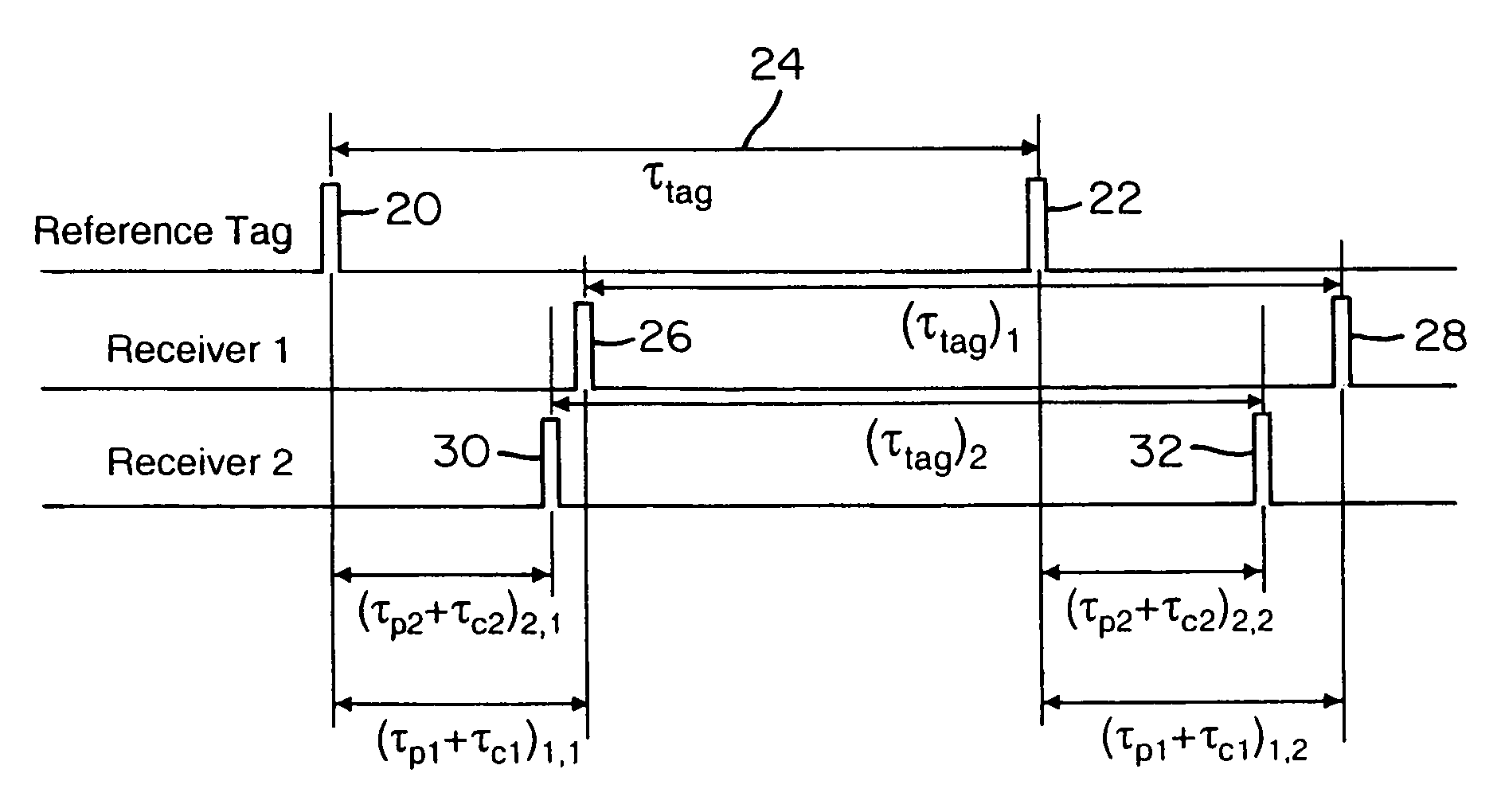
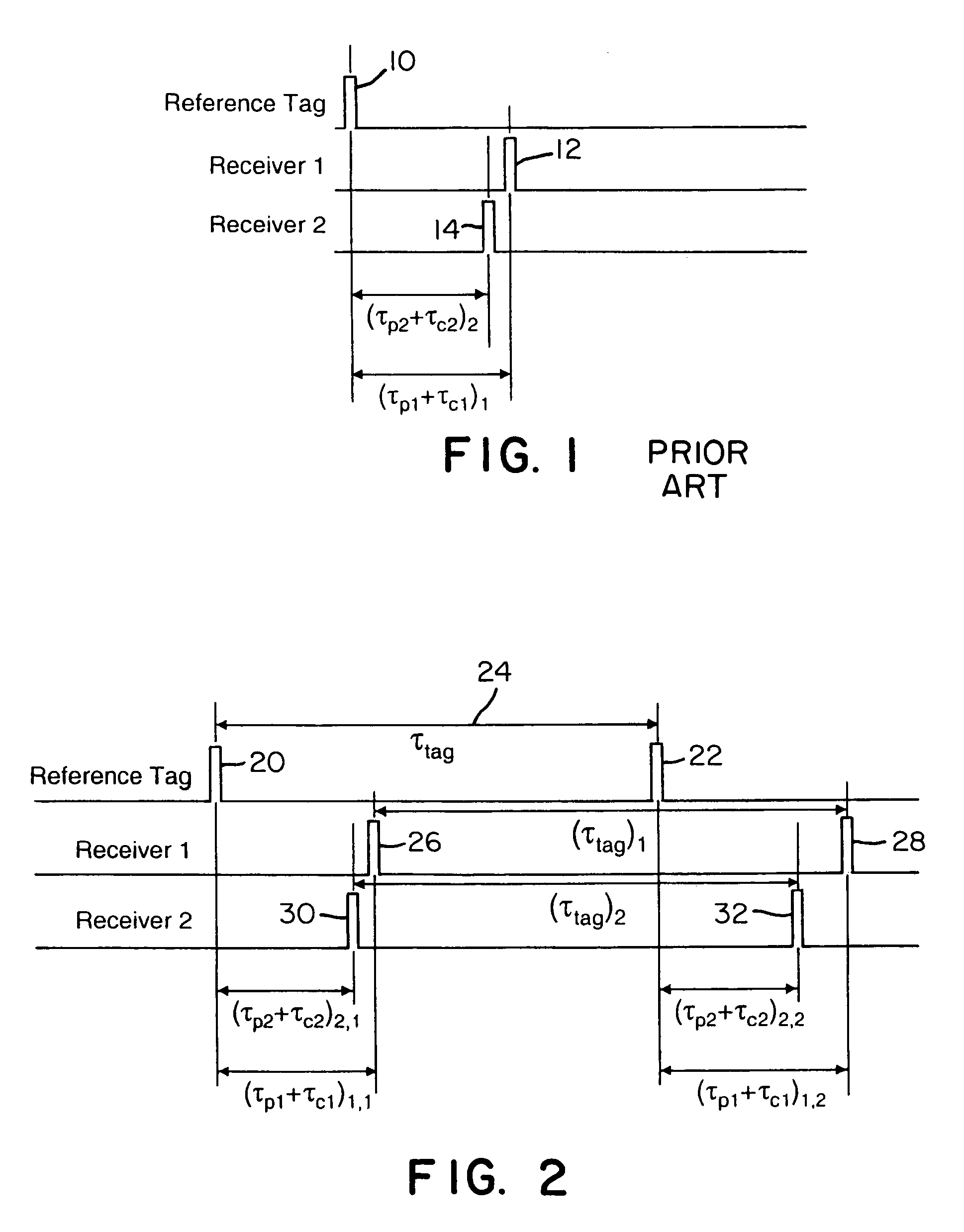
[0028]To help place the invention in perspective, Anderson '409 describes a “zeroth order” technique in which times-of-arrival of a reference tag signal (as observed at spatially-located receivers) are precisely aligned using a priori knowledge of the reference tag and receiver positions (hence, a priori knowledge of reference tag propagation times from the reference tag transmitter to the individual receivers) and AP node to C node cable delays. However, as indicated above, even a small frequency offset between receiver timing circuits causes this calibration to be quickly lost.

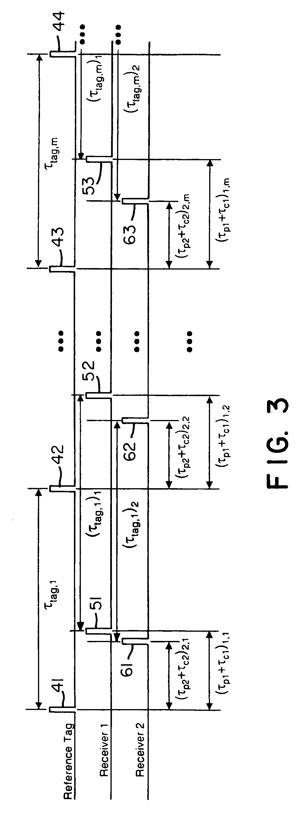
[0029]Instead of determining timing alignment of remote clocks in multiple receivers based on time-of-flight measurement of a reference pulse and a priori knowledge of positions of the reference tag and the receivers, the present invention utilizes a relatively fixed time reference interval and a constant or known frequency offset between respective local clocks and / or higher order differences (e.g., frequen...


PUM


Abstract

Instead of normalizing time reference of independent spatially-located clocks using a reference tag transmission from known location, the present invention uses an interarrival time interval between a pulse pair of UWB pulses as a timing metric. Thus, a method of synchronizing spatially-located clock or normalizing time indications thereof comprises transmitting a UWB pulse pair, determining at first and second monitoring stations a respective count value indicative of a locally measured time interval between received pulse pairs, determining a ratio between clock counts of first and second monitoring stations, and utilizing the ratio to determine clock skew, e.g., a timing correction to be applied to respective local clocks of the monitoring stations. A corresponding system comprises a reference tag transmitter that transmits a pulse pair of UWB pulses to define a time reference interval, a first independent receiver that receives the pulse pair to generate a first count value indicative an interarrival interval between the pulse pair, a second independent receiver that receives the pulse pair to similarly generate a second count value, and a processor hub responsive to the count values to determine a ratio corresponding to the ratio of respective clock frequencies of the first and second receiver clocks. Once the correction is applied, time-of-arrival information from object tag transmissions may be used to determine object location with sub-foot position accuracies.

Description

CROSS-REFERENCE TO RELATED PATENTS AND PATENT APPLICATIONS[0001]This invention is related to commonly-owned U.S. Pat. No. 6,882,315 (Richley, et al.) issued Apr. 19, 2005 entitled “Object Location System and Method,” which is incorporated herein by reference. This invention also claims the benefit of Provisional Application 60 / 752,950 filed Dec. 23, 2005 and entitled “Wireless Object Location System and Method.”BACKGROUND[0002]This invention concerns timing synchronization or determination of time corrections to be applied to timing devices of independent RF receivers generally, but is disclosed herein in connection with implementation in a wireless object location system and method.[0003]In U.S. Pat. No. 6,882,315 (“the '325 patent”), a precision object location system is described in which cycling of local clocks of multiple receivers was frequency-locked (but not necessarily phase-locked) with a common clock frequency (e.g., where a common clock signal is conveyed over low-cost C...

Claims


Application Information

Patent Timeline
Patent Type & Authority Patents(United States)
IPC IPC(8): G01S3/02
CPCG01S5/0009G01S5/021G01S5/14
Inventor AMETI, AITANCHEN, KEMINGFONTANA, ROBERT J.RICHLEY, EDWARD A.TURNER, BELINDA
Owner ZEBRA TECH CORP
Why Eureka
Try Eureka