Method of creating a roof venting space

a technology for venting space and construction brackets, which is applied in the field of construction brackets for roofs and construction brackets for roof rafters, can solve the problems of water damage to roofs, roof structures, internal walls and ceilings, and blockage of ridge vents, so as to facilitate the rafter construction/assembly process, reduce possible heat loss through the bracket, and save time

Inactive Publication Date: 2009-02-24
FENNELL JR HARRY C
View PDF46 Cites 26 Cited by
  • Summary
  • Abstract
  • Description
  • Claims
  • Application Information

AI Technical Summary

Benefits of technology

[0015]It is an object of the present invention to provide a construction bracket that provides a more efficient way of connecting roof rafters by decreasing framing time and reducing the number of angle cuts required to fabricate sloped roofs. It is another object of the present invention is to provide a construction bracket that eliminates the need for compound angle cuts on rafter ends for roof hips and valleys. It is still another object of the present invention to provide a construction bracket that allows for easier attachment of light framing to large structural members at angled building configurations. It is a further object of the present invention to provide an internal ducting system for venting a roof that is more aesthetic than external systems and does not increase the height of the ridge. It is yet a further object of the present invention to provide improved airflow in a ventilated roof, even roofs with multiple gables, hips and / or valleys. It is another object of the present invention to provide proper roof ventilation even when the roof is covered with snow.
[0016]The present invention achieves these and other objectives by providing a construction bracket that has at least a first flange and a second flange connected to each other along one edge of each flange forming a “V” shaped bracket, which is either at a fixed or an adjustable angle. In its simplest configuration, the first flange is configured to connect to the end of a roof rafter that is square cut. An end having a square cut is one whose end is substantially perpendicular to the length of the board. The second flange is configured to connect to the end of a second roof rafter that is the opposing rafter to the one attached to the first flange, or in the case of a shed roof, to a header board. Because the need to make angled or compound angle cuts to the ends of the rafters forming the roof structure is eliminated, the time required to frame a roof is decreased thus providing a savings on labor cost.
[0017]Using a construction bracket of the present invention to join each paired rafter, or a shed roof rafter to a header board, creates a continuous internal space at the ridge, hip, or valley of a roof bounded by a covering such as the roof sheathing, which is typically plywood, or at the junction of the rafters of a shed roof with the header wall bounded by the shed roof sheathing. Unlike the typical construction structure where a ridge board, hip board or valley board is used to facilitate connecting the paired rafters together and creating a solid junction with the sheathing along these structures, this feature of the present invention, i.e. creating a continuous internal space along the rafter / rafter junctions, allows for improved airflow and roof ventilation even when the roof is covered by snow or when a large number of gables, ridges, hips, and valleys are present. This is so because no ridge vent is required. Gable end vents provide the vent outlet for the internal space. It also allows for improved airflow of shed roofs. An added feature is the improved aesthetic look of the roof line. Even in long, extended roof ridges, cupolas may be used to vent the roof at predetermined locations. The use of cupolas is an aesthetically pleasing and acceptable roof design feature.
[0019]In addition to the use of rafter joining boards, standard joist brackets may also be used to attach to the rafter joining boards to further facilitate the rafter construction / assembly process. In another embodiment, the construction bracket may have joist hangers attached directly to each of the first and second flanges or may be integrally formed with the construction bracket. In yet another embodiment of the present invention, the construction bracket may have a predetermined, continuous length capable of receiving a predetermined number of rafters. An advantage of this embodiment having a pivotable junction allows the framers to attach a predetermined number of rafters to the construction bracket and then raise this “pre-built” section of roof framing to the desired location. Markings may also be incorporated onto the surface of each flange at locations that match the proper construction code-defined spacing between each rafter to eliminate the need to measure, mark, and attach each rafter according to the required construction code spacing. This has the advantage of also saving time during the framing process.
[0020]For roofs of relatively low pitch, another embodiment of the present invention provides a way to insure that a sufficient internal space is formed between the rafters. In this embodiment, the construction bracket includes a base between the first and second flanges. In use, this embodiment has the shape of square-shaped “U” where the extending legs flare away from the inside of the “U”. The base, which corresponds to the bottom of the square-shaped “U”, provides the necessary spacing between the first and second flanges to create a sufficient internal volume between the rafters. Like the V-shaped construction bracket of the present invention, the first and second flanges may be fixedly attached to each side of the base or they may be pivotably attached allowing for a range of roof pitches.
[0021]The U-shaped bracket of the present invention may also have the additional features that the V-shaped bracket may have as described above. Both the U-shaped and V-shaped brackets may incorporate a predetermined amount of insulation at the bottoms of the brackets to further reduce possible heat loss through the bracket. The U-shaped bracket may be further configured to accommodate a ridge beam against the outside surface of the base.

Problems solved by technology

The formation of ice results from a lack of free flowing air from the eaves to the ridge of the roof.
Water then backs up under the shingles causing water damage to the roof, roof structure and internal walls and ceilings.
There are several disadvantages of using ridge vents.
In cold climates, snow may accumulate on the roof and the ridge vent, thus blocking the ridge vent.
Blocking of the ridge vent prevents proper venting of the roof that leads to the formation of ice dams.
This creates venting problems for construction designs that incorporate large numbers of gables and no attic space between the rafters and ceiling joists.
Further, ridge vents create a ridge line that is not aesthetically pleasing.
Both of these device suffer from the same disadvantages described earlier, i.e., the problem of snow accumulation blocking ventilation along the ridge and the unaesthetic look of a ridge vent.
Consequently, the proper venting of a roof continues to be a problem.
Not only is roof venting a problem, but also connecting one rafter to another requires that the rafters be attached securely.
A disadvantage of these connector devices is the need to cut the butting end of the joist or rafter at the proper angle for attachment to a ridge board or other joist.
Another disadvantage is the time required to perform the cut of the joist or rafter at the proper angle for attachment to these connector devices.

Method used


Image

  • Method of creating a roof venting space
  • Method of creating a roof venting space
  • Method of creating a roof venting space

Examples


Embodiment Construction

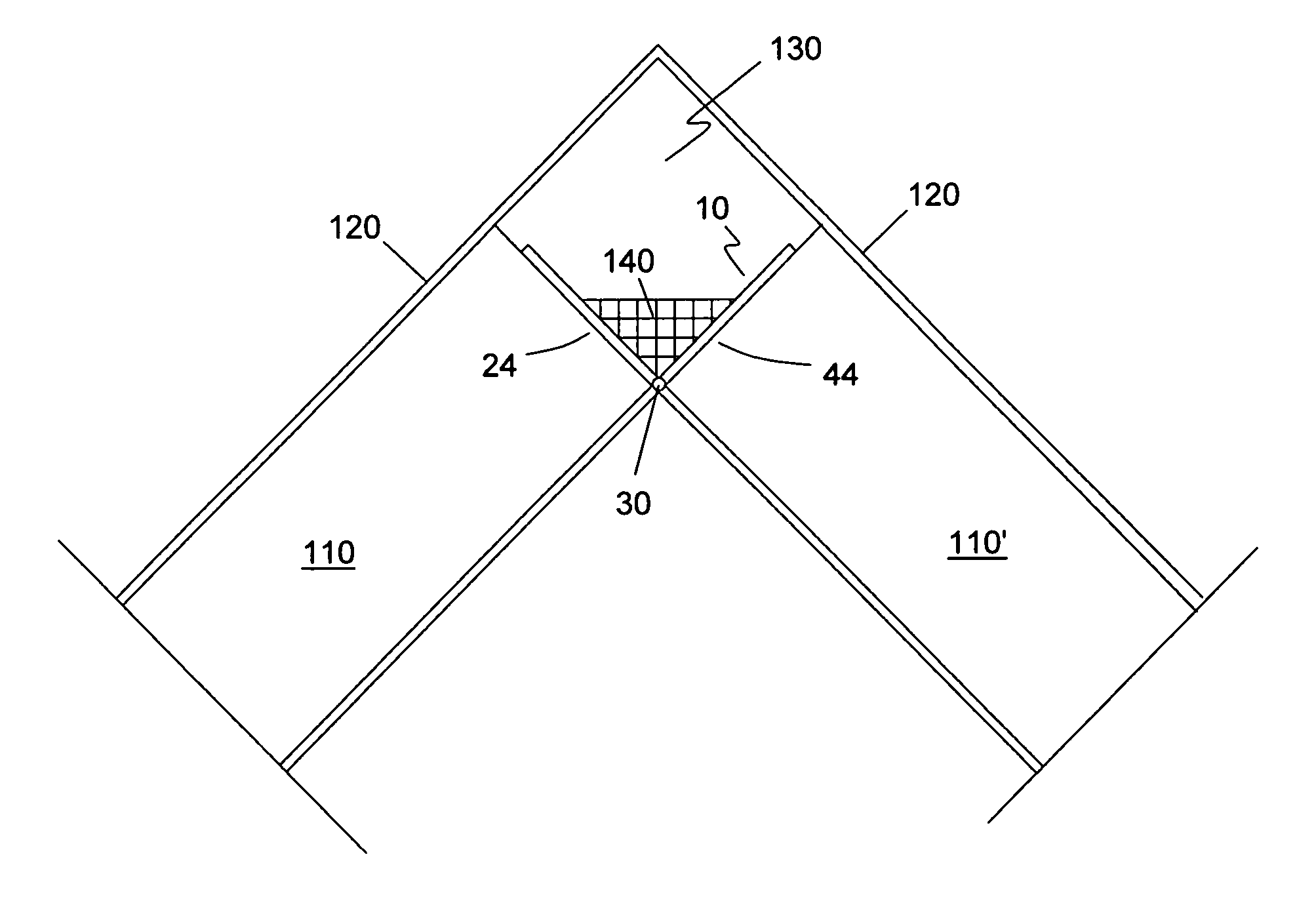
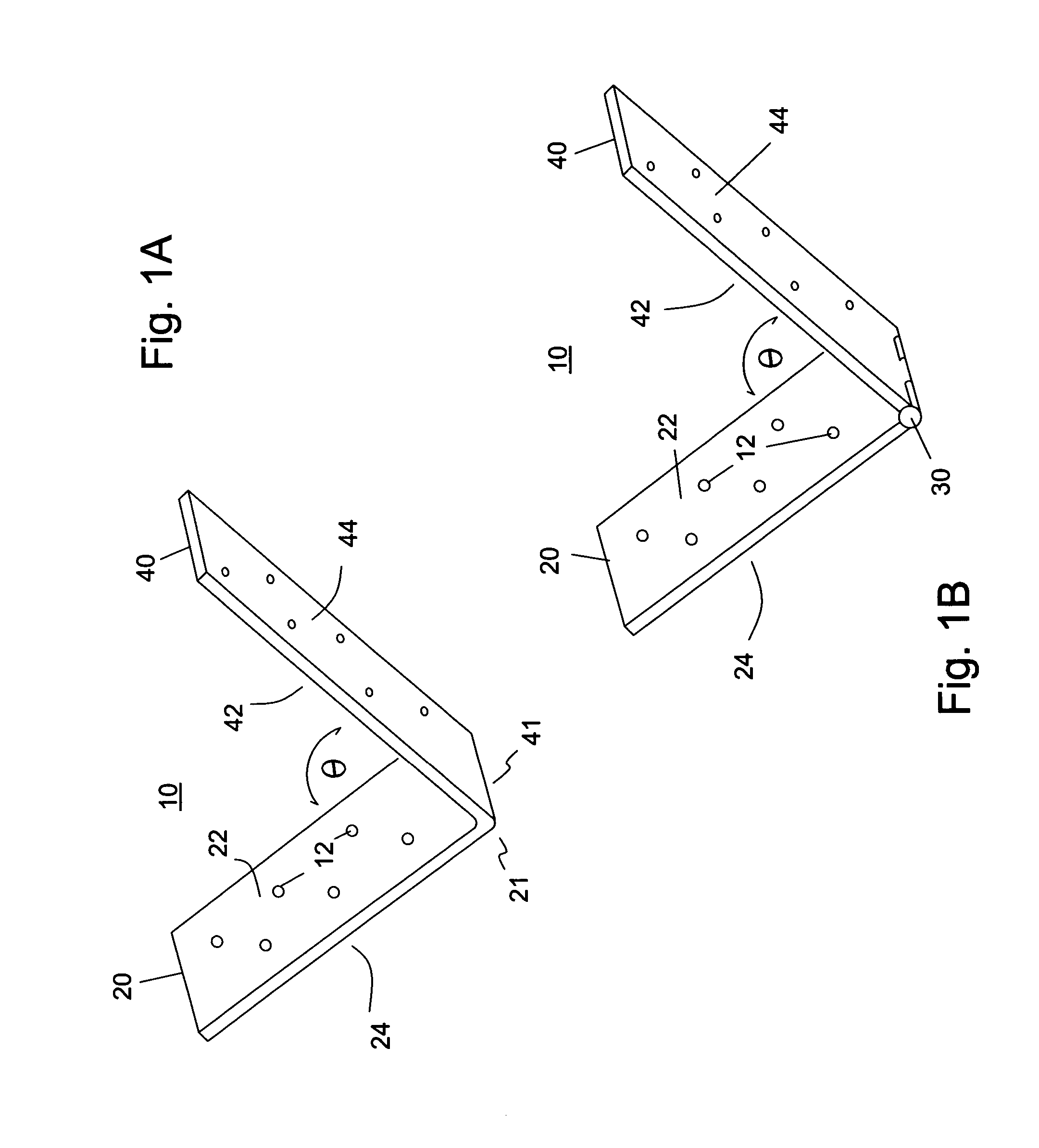
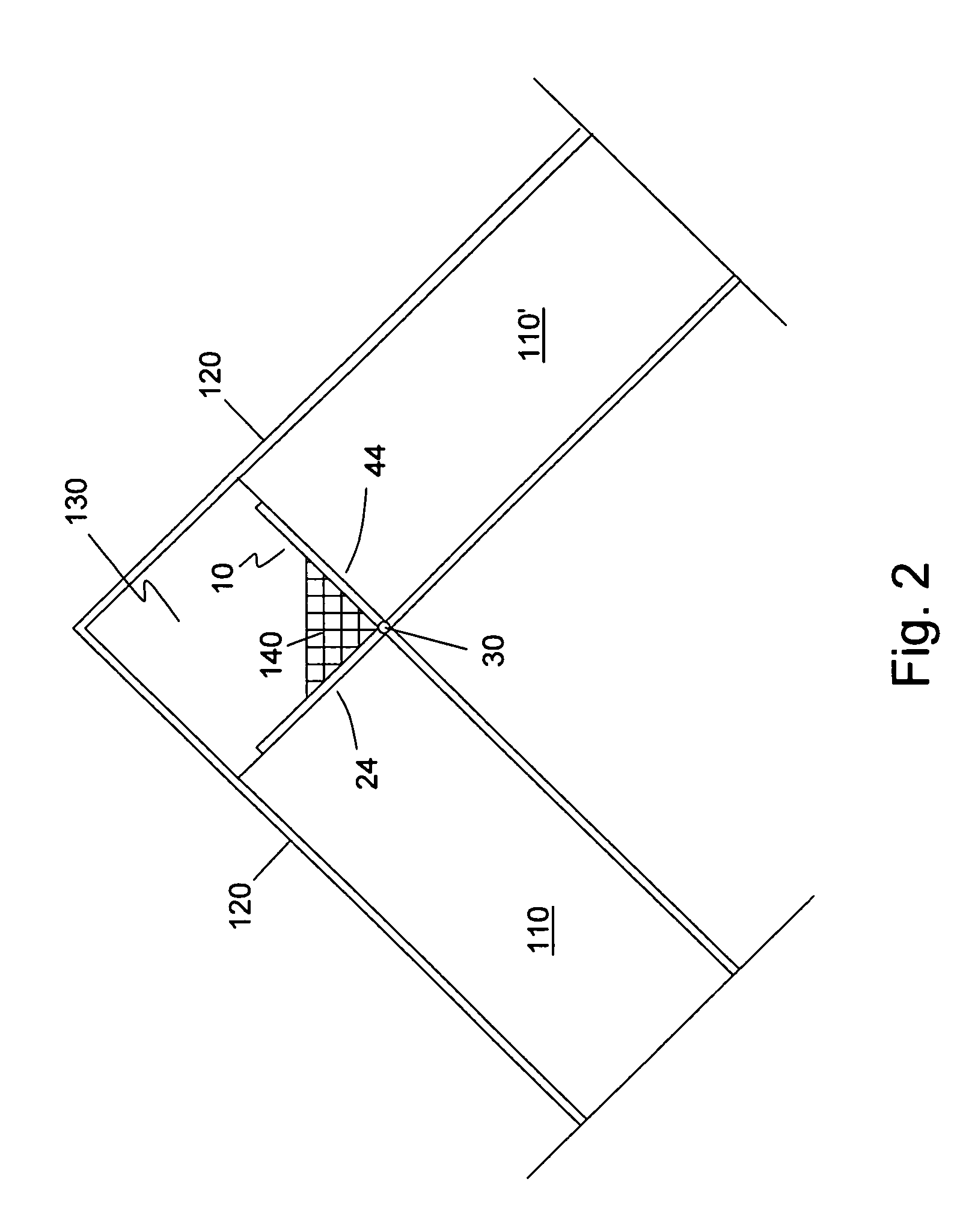
[0033]The preferred embodiment(s) of the present invention are illustrated in FIGS. 1-9. FIG. 1A shows a perspective view of a simplified construction bracket 10 of the present invention. Construction bracket 10 includes a first flange 20 having first flange edge 21, a first flange inside surface 22 and a first flange outside surface 24 (not shown), and a second flange 40 having a second flange edge 41, a second flange inside surface 42 (not shown) and a second flange outside surface 44. First flange 20 and second flange 40 are joined along first flange edge 21 and second flange edge 41. Construction bracket 10 may be constructed by connecting first flange 20 to second flange 40 by any means known to those skilled in the art for attaching one flange to another flange. If construction bracket 10 is made of metal, first flange 20 may be welded to second flange 40 at a predetermined angle of separation θ. Construction bracket 10 may also be formed as a single piece such as by casting o...


PUM


Abstract

A method of creating a roof venting space includes assembling a plurality of roof rafters where at least one end of the plurality of roof rafters are assembled to a surface to define a space between the one end of the plurality of roof rafters and the surface, attaching roof sheathing to the outside of the plurality of roof rafters where the roof sheathing covers the space creating a continuous internal ducting space, and connecting a vent to the continuous internal ducting space.

Description

[0001]This application claims the benefit of U.S. Provisional Patent Application No. 60 / 509,618, filed Oct. 8, 2003.BACKGROUND OF THE INVENTION[0002]1. Field of the Invention[0003]The present invention relates generally to construction brackets for framing. Particularly, the present invention relates to construction brackets for a roof. More particularly, the present invention relates to construction brackets for roof rafters for more efficient construction and for venting of roofs.[0004]2. Description of the Prior Art[0005]In wood frame building construction, a plurality of paired roof rafters are connected together forming a roof structure. Typically during construction, a ridge board is used to facilitate the roof rafter framing process. Roofs are typically vented to prevent excess heat and associated problems such as increased cooling costs in hot climates and ice formation on the roof in cold climates. The formation of ice results from a lack of free flowing air from the eaves ...

Claims


Application Information

Patent Timeline
Patent Type & Authority Patents(United States)
IPC IPC(8): E04D13/00F24F7/02E04B1/38E04B1/58E04B7/00E04B7/02
CPCE04B7/02E04B2001/2644E04B2001/5868
Inventor FENNELL, JR., HARRY C.
Owner FENNELL JR HARRY C
Why Eureka
Try Eureka