
Apparatus and method for making an improved chain link fabric

a chain link fabric and flattening technology, applied in the field of chain link fabrics, can solve the problems of easy crushing or bending of the ends, the damage may be so severe, and the weak knuckled or barbed ends are easily crushed or bent out of place, so as to reduce the total cost of the fabric and the time required for installation and repair, and the effect of enduring large amounts of for

Active Publication Date: 2009-02-24
BERGANDY MACHINERY
View PDF29 Cites 4 Cited by
  • Summary
  • Abstract
  • Description
  • Claims
  • Application Information

AI Technical Summary

Benefits of technology

"The present invention is an improved chain link fabric with flattened end portions that do not pose a risk of serious harm to installers or individuals who come into contact with the flattened end portions. The flattened end portions can withstand large amounts of force without being bent or pulled apart. The chain link fabric can be quickly and easily prepared for shipping and installation without the end portions tangling. The invention eliminates the need for tension wires, top rails, crimping wires, and other equipment that adds cost and complexity to the fabric. The invention also provides a compressing assembly to remove sharp edges from the welded wire-end portions. The compressing assembly includes a stabilizing die, a lever, and a die plate to interface with the chain link fabric. The technical effects of the invention include stronger, more stable flattened end portions that can withstand more force, a simplified and cost-effective process for preparing the fabric, and a more aesthetically pleasing appearance."

Problems solved by technology

One such drawback is that knuckled or barbed ends are weak and easily can be crushed or bent out of place.
When someone or something comes into contact with the barbed or knuckled ends of chain link fabric, the ends may be crushed or bent out of place.
Either way, the damage may be so severe that the fabric must be repaired or replaced.
Additionally, if the ends of the fabric protrude because they have been bent out of place, the fabric has an undesirable, if not unsightly appearance.
The protruding ends of the fabric are also more likely to cause injury because individuals passing by are more likely to come into contact with them.
The protruding ends can poke individuals who do not notice them, causing serious injury.
The protruding ends of a damaged chain link fabric can poke an individual trying to climb the fence in a sensitive area, for example, the eye, or catch on to the individual's clothing as he is climbing the fence, causing the individual to fall and be seriously injured.
The additional risk of injury and the undesirable appearance that results when the barbed and knuckled ends of the fabric are damaged can result in additional time being spent and expenses being incurred to repair or replace the damaged chain link fabric.
Another drawback of the chain link fabric described above, is the difficulty associated with shipping, installing, and removing it.
However, the knuckled or barbed ends of these compacted rolls usually become tangled in the rest of the chain link fabric, causing the ends to be bent out of place or pulled apart.
Alternatively, if the fabric is attached to a fence frame or other type of support member, when separate frames are placed close to one another the knuckled and barbed ends of the different chain link fabrics can get tangled together and pulled apart.
The damaged ends of the fabric may require repair, resulting in additional time being spent and expenses being incurred.
Additionally, individuals who install and repair the fabric are exposed to the additional risk of being seriously injured by the sharp barbed and knuckled ends that must be untangled, repaired, and installed.
One such disadvantage is that many of these fabrics, such as gabion, are made of a very light gauge wire (typically 9 to 11 gage), which cannot be an effective permanent barrier and is more expensive to use.
The flattened end portions of fabrics, other than gabion, typically are not strong enough to resist large forces, (e.g., an individual climbing onto the fabric) without bending or crushing.
Even though a ¼″ rod is sometimes use to strengthen the fabric, the rod usually does not provide enough strength to allow the fabric to resist large forces.
Therefore, through regular use, these fabrics usually experience a large amount of force at some time during their useful life.
As a result, these fabrics usually are crushed or bent when a large force is exerted on them.
The bent or crushed fabric must then be repaired or replaced resulting in additional time being spent and expenses being incurred.
Yet another disadvantage associated with chain link fabrics that might be categorized as having flattened end portions is that they often have protrusions and sharp edges at the ends of the adjoined wire-end portions resulting from a straight cut that can cause serious injury.
More specifically, the flattened end portions are typically butt welded together, i.e., the ends of the flattened end portions are aligned with one another, without overlapping, during the welding process, or lap welded together, i.e., the flattened end portions overlap one another during the welding process, in a manner that leaves sharp edges and protrusions that are dangerous.
Over an extended period of time, these protrusions and sharp edges can result in serious injury to numerous individuals.
This is especially true when the individuals nearby do not see the protrusions, or do not appreciate the harm that they can cause (e.g., harm to small children and young adults).
Therefore, fabrics having sharp edges and protrusions create an increased risk of injury when they are located near schools or in other areas where large numbers of children likely are to be present.

Method used


Image

  • Apparatus and method for making an improved chain link fabric
  • Apparatus and method for making an improved chain link fabric
  • Apparatus and method for making an improved chain link fabric

Examples


Embodiment Construction

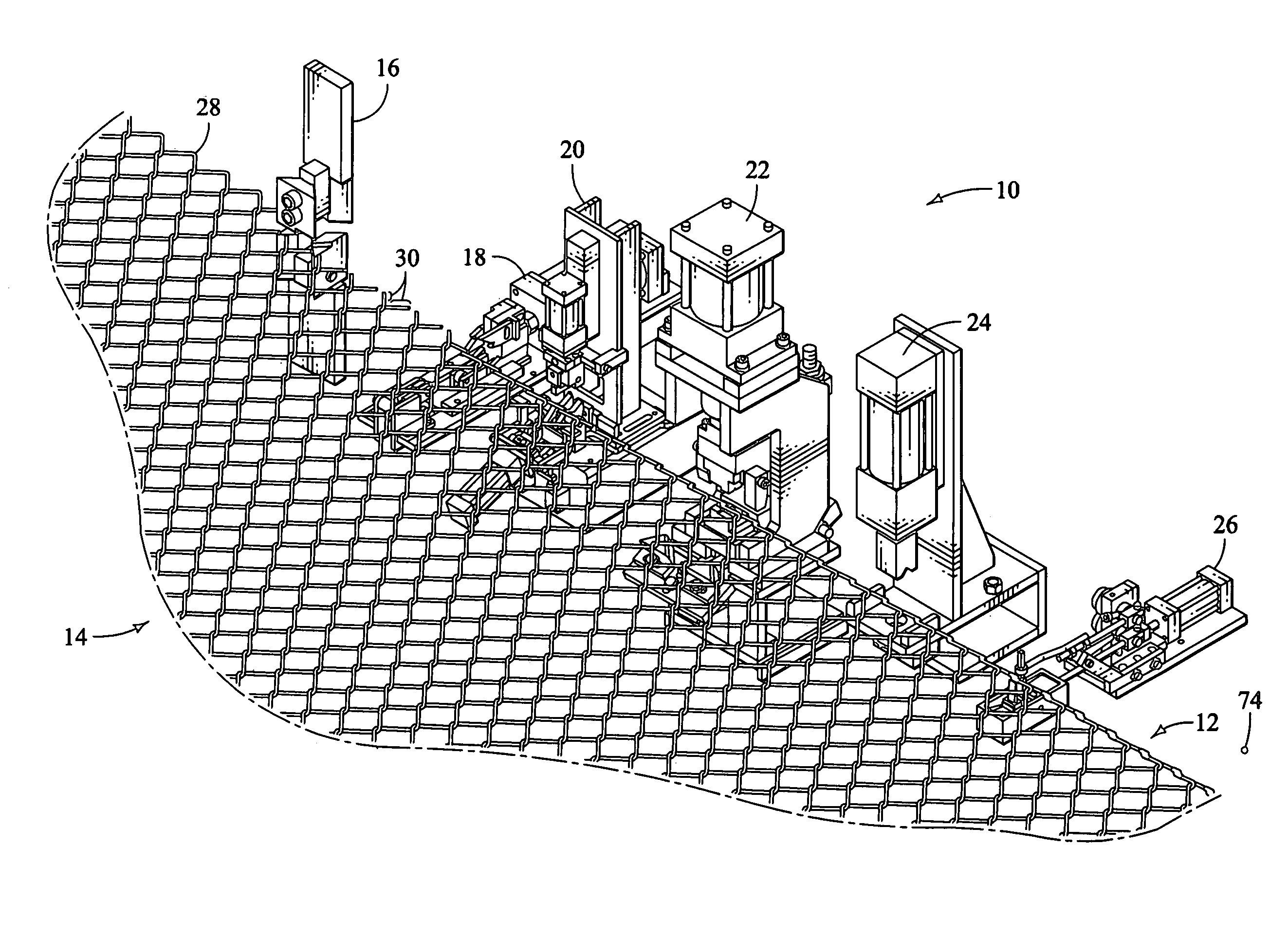
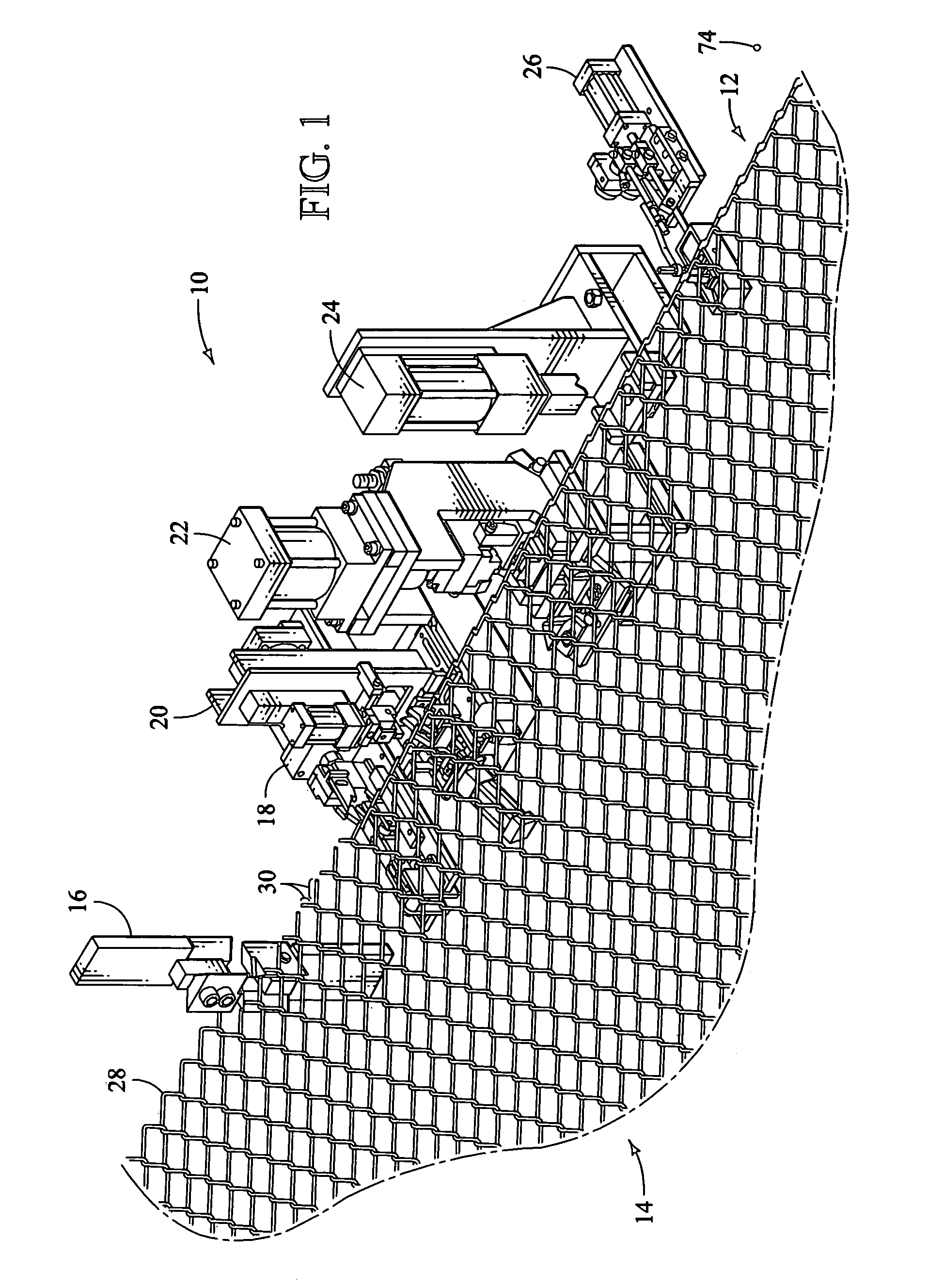
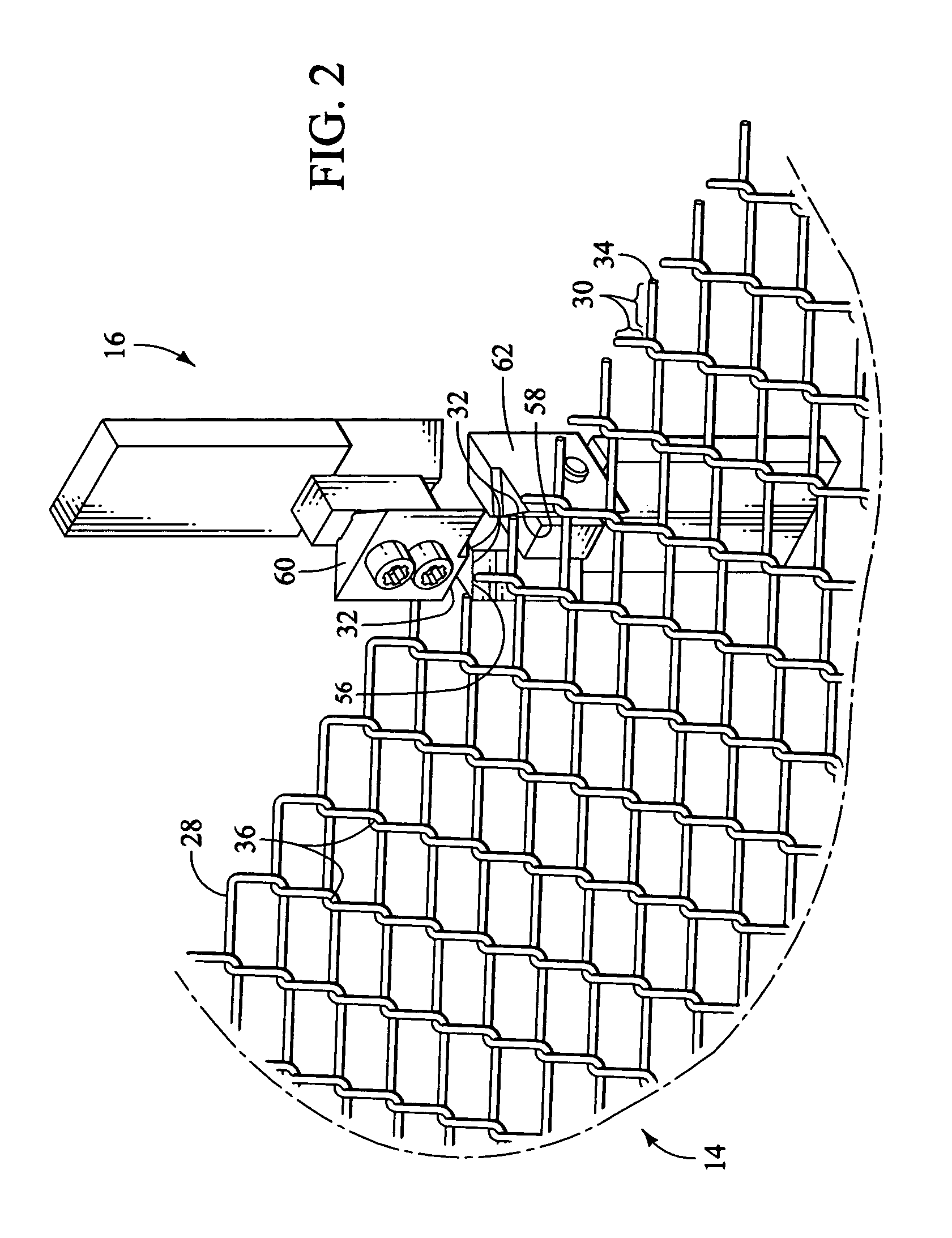
[0048]The present invention provides for an improved chain link fabric having flattened end portions and a method and apparatus for making the flattened end portions. The method and apparatus for making flattened end portions and the chain link fabric itself, described herein, provide a number of significant advantages. By way of example only, some of the advantages of the present invention include, extending the useful life of the fabric and reducing the need to replace or repair the fabric; providing an aesthetically pleasing, taut fabric with flattened end portions that are strong enough to resist a large force without becoming bent or crushed; preventing serious injury to installers and those who come into contact with the chain link fabric by providing a fabric without sharp or protruding edges; providing a fabric that does not tangle and can be quickly and safely prepared for shipping and installation; and reducing the expense and repair associated with traditional chain link ...


PUM

PropertyMeasurementUnit
forceaaaaaaaaaa
durableaaaaaaaaaa
movementaaaaaaaaaa

Abstract

An apparatus for processing chain link fabric including a welding assembly and / or a compressing assembly. The welding assembly is configured to weld together wire-end portions of the chain link fabric. The welding assembly includes a guiding assembly having a finger and a cam, which are configured to restrict the movement of the wire-end portions while the welding assembly welds them together. The finger and the cam are configured to move relative to the wire-end portions both before and after the wire-end portions are welded together. The compressing assembly is configured to compress the wire-end portions after they are welded together. The compressing assembly includes a stabilizing assembly having a stabilizing die, which is configured to interface with the chain link fabric and to restrict the movement of the welded wire-end portions while the compressing assembly compresses the welded wire-end portions.

Description

CROSS-REFERENCE TO RELATED APPLICATION[0001]This is a continuation-in-part application of U.S. patent application Ser. No. 10 / 350,142, filed on Jan. 22, 2003, now abandoned entitled: “METHOD AND APPARATUS FOR MAKING AN IMPROVED CHAIN LINK FABRIC,” by Jose G. Garcia and Scott C. Barsotti, which application is incorporated by reference herein.BACKGROUND OF THE INVENTION[0002]1. Field of the Invention[0003]The present invention relates generally to chain link fabrics and, more particularly, to an improved chain link fabric with flattened ends and a method and apparatus for forming the flattened ends of the fabric.[0004]2. Description of the Related Art[0005]It has been estimated that throughout the world, millions of square feet of chain link fabric are produced and sold annually. Recognizing the importance of providing effective and durable chain link fabric, the American Society for Testing and Materials (ASTM) has established minimum quality standards for both residential and commer...

Claims


Application Information

Patent Timeline
Patent Type & Authority Patents(United States)
IPC IPC(8): B21F27/14B21F27/02B21F29/00
CPCB21F27/02B21F27/14B21F29/00
Inventor GARCIA, JOSE G.BARSOTTI, SCOTT C.
Owner BERGANDY MACHINERY
Learn More