Shock absorber with integrated displacement sensor

a technology of displacement sensor and shock absorber, which is applied in the direction of shock absorbers, mechanical equipment, transportation and packaging, etc., can solve the problem that known displacement sensors such as described above can be expensiv

Inactive Publication Date: 2009-02-24
TENNECO AUTOMOTIVE OPERATING CO INC
View PDF12 Cites 23 Cited by
  • Summary
  • Abstract
  • Description
  • Claims
  • Application Information

AI Technical Summary

Problems solved by technology

However, known displacement sensors such as described above can be expensive due to the large number of parts involved, the amount of labor required to mount the sensor, and the necessity of calibrating the sensor after the vehicle exits the manufacturing production line.

Method used


Image

  • Shock absorber with integrated displacement sensor
  • Shock absorber with integrated displacement sensor
  • Shock absorber with integrated displacement sensor

Examples


Embodiment Construction

[0016]One embodiment of the present invention is a shock absorber mounted on a vehicle that has a piston rod that is magnetically encoded. The magnetically encoded piston rod allows the position of the piston rod relative to the shock absorber cylinder to be determined, thus providing a displacement sensor integrated into the shock absorber for the vehicle.

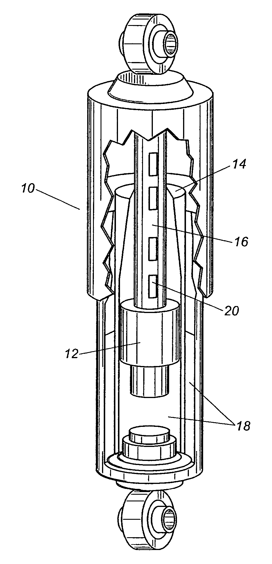
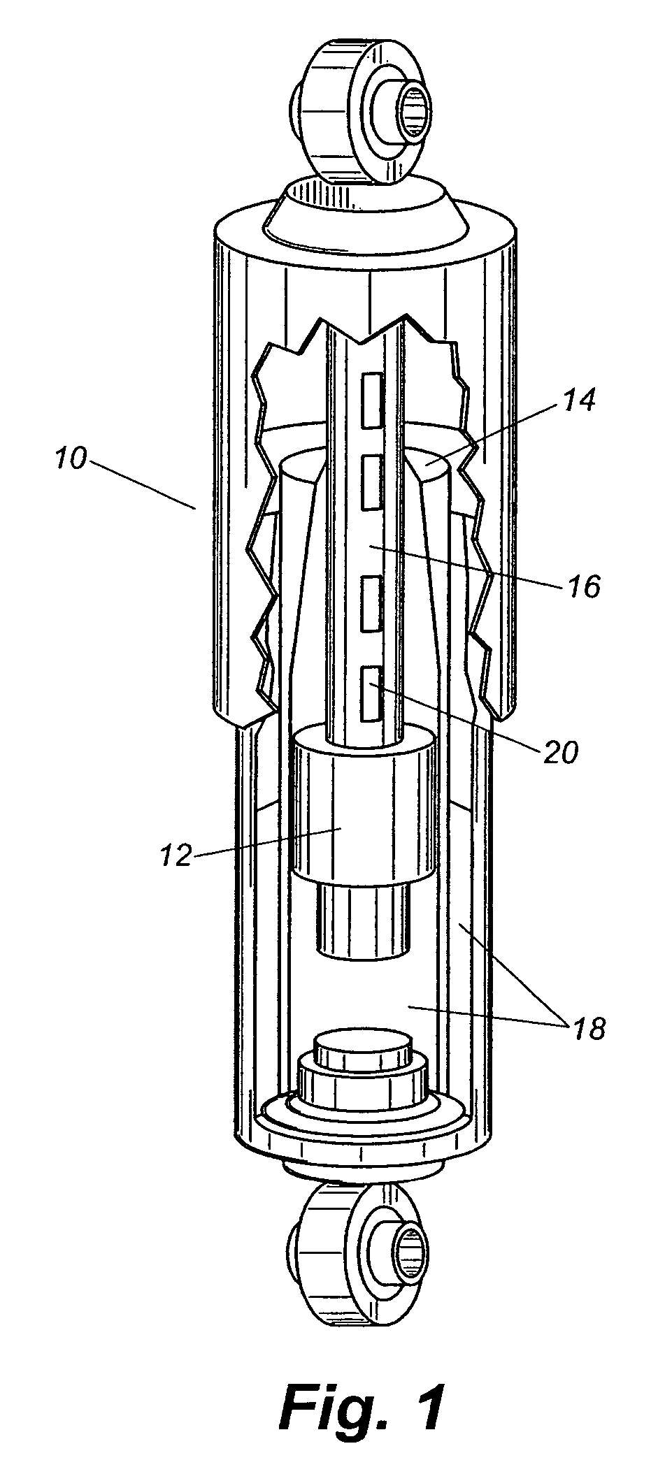
[0017]FIG. 1 is a cut-away diagram of a shock absorber 10 in accordance with one embodiment of present invention. Shock absorber 10 includes a piston 12, a cylinder 14, a piston rod 16, and oil 18. Shock absorber 10 functions in a known manner to absorb shock in a vehicle.

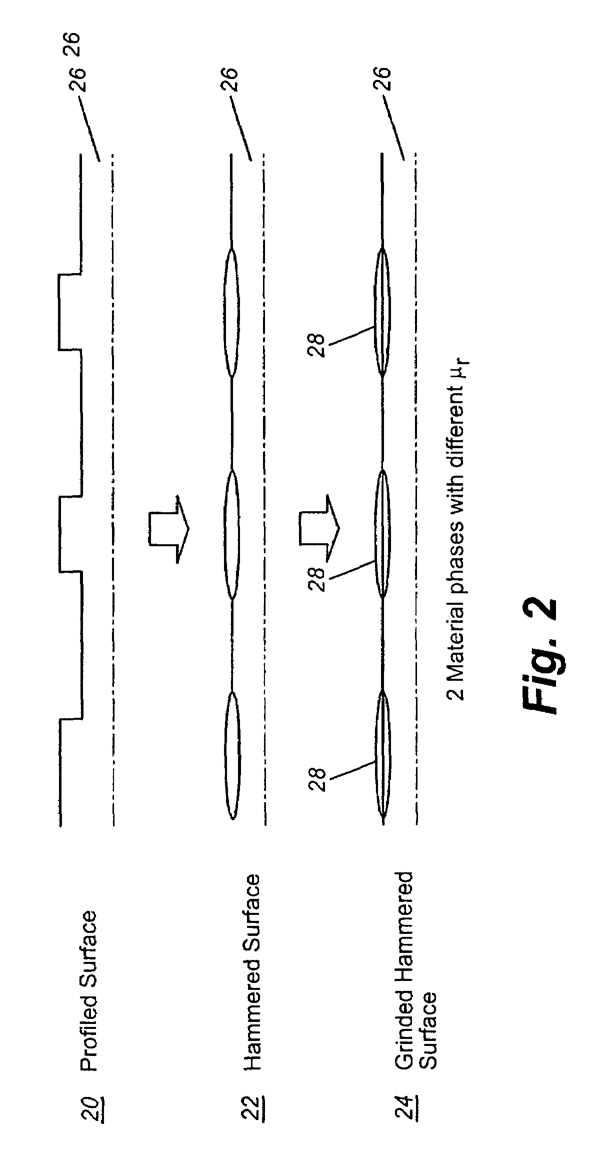
[0018]Piston rod 16 is encoded with magnetic material 20 that allows shock absorber 10 to also function as a displacement sensor. The encoded magnetic material 20 of piston rod 16 produces local material phase changes at the surface of piston rod 16, which results into transitions of material phases with high and low magnetic permeability. When the difference in ...


PUM


Abstract

A shock absorber include a cylinder, a piston rod coupled to the cylinder, and a piston coupled to the piston rod. The piston rod is magnetically encoded so that it includes a plurality of magnetic phase shifts. The phase shifts allow the position of the piston rod relative to the cylinder to be determined so that it can function as a displacement sensor.

Description

RELATED APPLICATIONS[0001]This application claims the benefit of U.S. Provisional Patent Application No. 60 / 587,552 filed Jul. 14, 2004, the specification of which is herein incorporated by reference.FIELD OF THE INVENTION[0002]One embodiment of the present invention is directed to a shock absorber for a vehicle. More particularly, one embodiment of the present invention is directed to a shock absorber for a vehicle that includes an integrated displacement sensor.BACKGROUND INFORMATION[0003]A number of vehicle / automotive applications require as an input signal the distance between the vehicle body (i.e., the sprung mass) and the suspension (i.e., the non-sprung mass). Examples of such applications include automated vehicle leveling systems, semi-active and active suspension systems, and leveling systems for high-intensity discharge headlights.[0004]In known applications, the input signal is usually provided by separately mounted displacement sensors. These sensors are typically moun...

Claims


Application Information

Patent Timeline
Patent Type & Authority Patents(United States)
IPC IPC(8): F16F15/03
CPCB60G17/01933F16F9/3221F16F9/3292B60G2204/112B60G2400/252B60G2401/17F15B15/28F16F9/00F16F9/32
Inventor SAS, GEERTMAES, MARIOLAUWERYS, XAVIERMERMANS, POLCHIARADIA, DAVID
Owner TENNECO AUTOMOTIVE OPERATING CO INC
Why Eureka
Try Eureka