Fluidic interventional device and method of distal protection

Inactive Publication Date: 2009-02-24
SPRITE SOLUTIONS
View PDF3 Cites 107 Cited by
  • Summary
  • Abstract
  • Description
  • Claims
  • Application Information

AI Technical Summary

Benefits of technology

[0017]In contrast to hydraulically powered catheters of the prior art which rely on one or more “free” jets the present invention relies on the wall attachment effect to produce a jet which interacts with and propels material from the body.
[0018]In general, the wall attachment effect takes place when a preferably annular sheet of fluid attaches to a wall after being injected at high pressure into a fluid medium. It is a property of such an att

Problems solved by technology

One problem with these prior art approaches is the inability

Method used


Image

  • Fluidic interventional device and method of distal protection
  • Fluidic interventional device and method of distal protection
  • Fluidic interventional device and method of distal protection

Examples


Example

Overall System Architecture

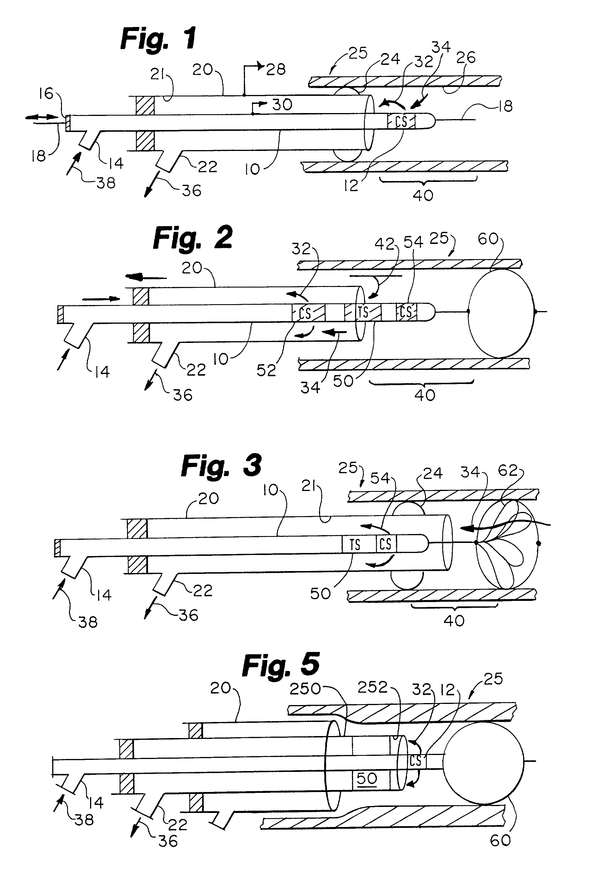
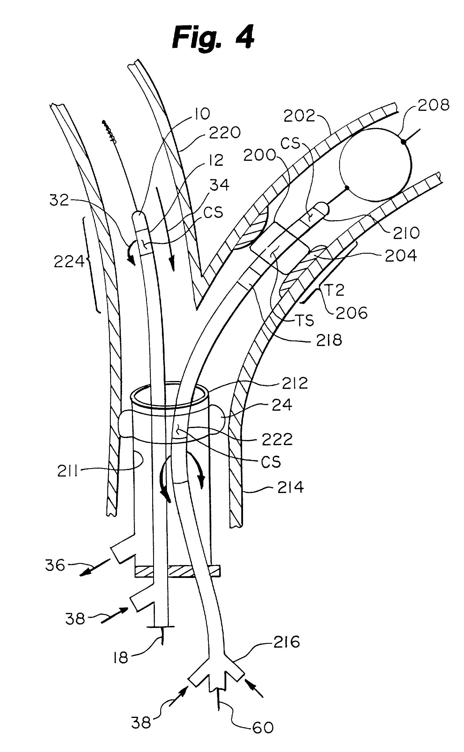
[0046]FIG. 1 through FIG. 5 show several exemplary basic architectures for the fluidic interventional catheter system. In each figure, the system is shown within a blood vessel 25. In general the system is disclosed in the context of the treatment of coronary vessel disease and the system may be used in coronary arterial vessels of the heart and in saphanous veins harvested and implanted as coronary bypass vessels. The system may also be used in other vessels such as the carotids or other body lumens.

[0047]The fluidic interventional catheter 10 shown in FIG. 1 has one extraction section 12 located near the distal tip of the catheter. At the proximal end of the catheter 10 there is a fluid injection port 14 for the injection of primary fluid. The fluid injection port is in fluid communication with the extraction section 12 at the distal tip. In this version of the fluidic catheter there is a guidewire port 16 located at the proximal end of the catheter 10 f...


PUM


Abstract

A catheter for injecting and extracting fluids to interact with material at a treatment site in the body.

Description

CROSS REFERENCE TO RELATED APPLICATIONS[0001]This application is a Continuation-in-Part of U.S. patent application Ser. No. 09 / 995,303 filed Nov. 27, 2001 which is a Continuation of U.S. patent application Ser. No. 09 / 459,225 filed Dec. 10, 1999 now abandoned. The present application incorporates by reference these applications in their entirety.[0002]This application is a Continuation-in-Part of U.S. patent application Ser. No. 09 / 637,529 filed Aug. 11, 2000 which is incorporated by reference in its entirety herein.[0003]This application claims the benefit of U.S. Provisional Application Ser. No. 60 / 292,614 filed May 22, 2001 which is incorporated by reference in its entirety herein.[0004]This application claims the benefit of U.S. Provisional Application Ser. No. 60 / 262,866 filed Jan. 18, 2001 which is incorporated by reference in its entirety herein.[0005]This application claims the benefit of U.S. Provisional Application Ser. No. 60 / 293,856 filed May 25, 2001 which is incorporat...

Claims


Application Information

Patent Timeline
IPC IPC(8): A61M29/00A61M31/00A61B17/22A61B18/24
CPCA61B17/22012A61B17/221A61B17/32037A61B17/320758A61B18/245A61B2017/2215
Inventor BECK, ROBERT C.MISCHE, HANS
Owner SPRITE SOLUTIONS
Why Eureka
Try Eureka