Apparatus for detection of the gradient of a magnetic field, and a method for production of the apparatus

Active Publication Date: 2009-02-24
SENSITEC
View PDF15 Cites 29 Cited by
  • Summary
  • Abstract
  • Description
  • Claims
  • Application Information

AI Technical Summary

Benefits of technology

[0006]One object of the invention is to provide an apparatus for detection of the gradient of a magnetic field which produces reliable results when the magnetic fields to be detecte

Problems solved by technology

Conventional apparatuses admittedly achieve the necessary resolution, but problems occur as soon as there are interfering electromagnetic fields in the vicinity.
The required resolution is admittedly achieved by the use of SQUID sensors (SQUID=Superconduction Quantum Interference Device), but problems occur in the event of interference caused by electromagnetic fields in the vicinity.
These require cooling, which inc

Method used


Image

  • Apparatus for detection of the gradient of a magnetic field, and a method for production of the apparatus
  • Apparatus for detection of the gradient of a magnetic field, and a method for production of the apparatus
  • Apparatus for detection of the gradient of a magnetic field, and a method for production of the apparatus

Examples


first embodiment

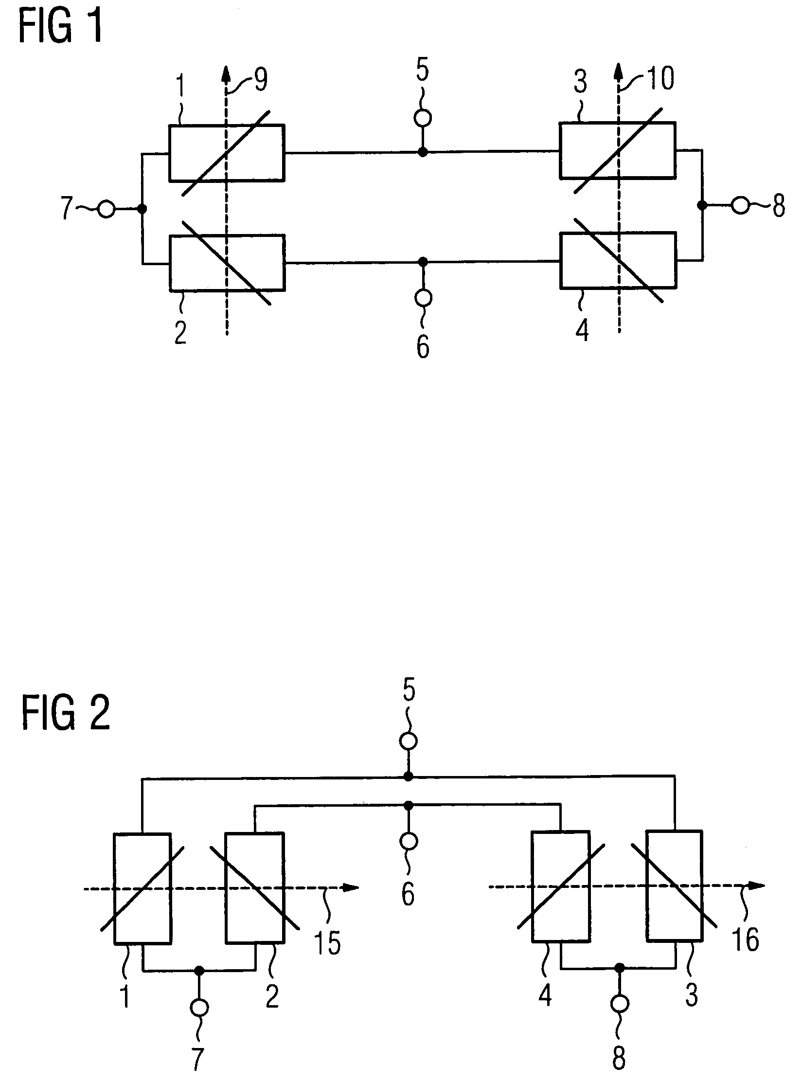
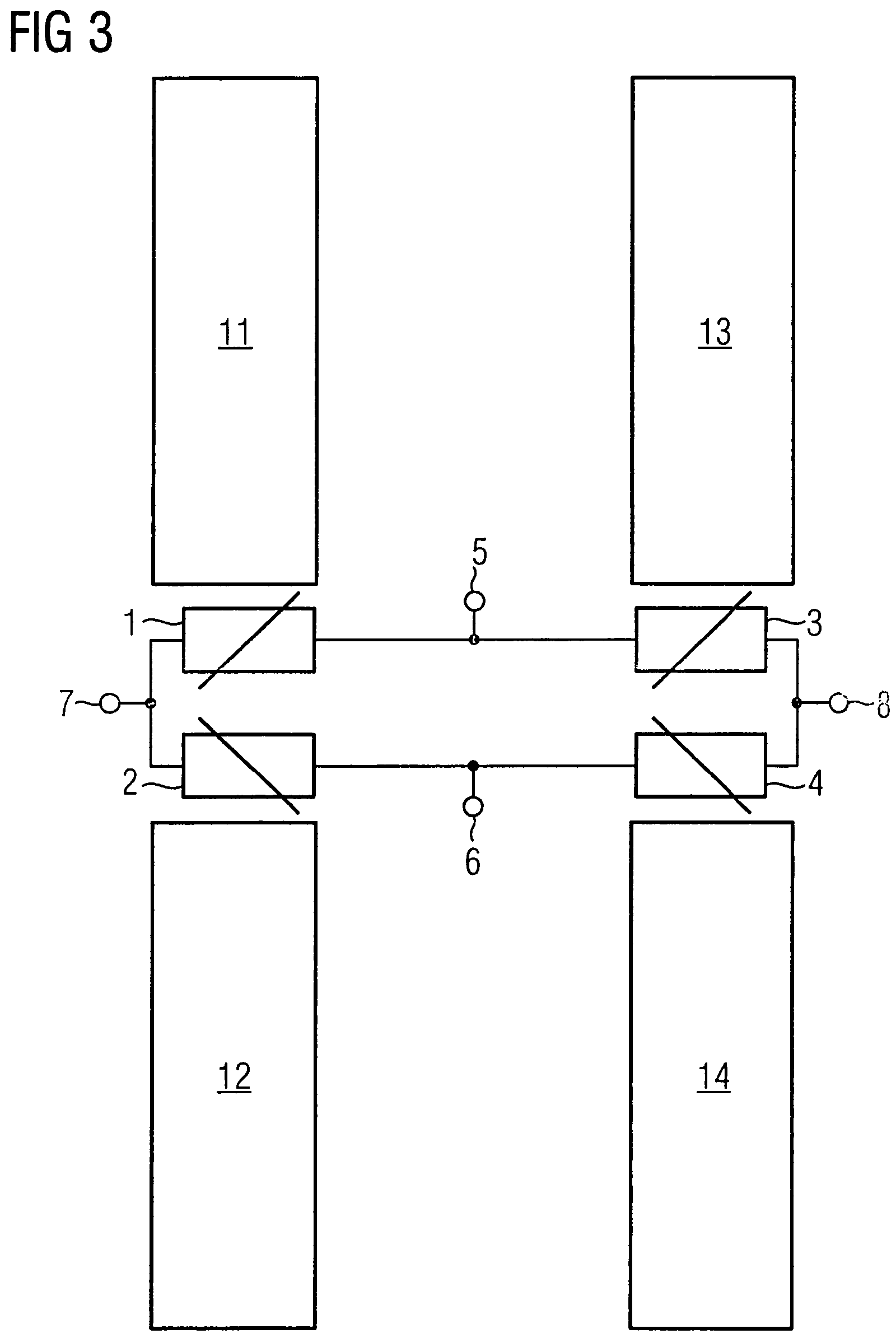
[0076]FIG. 1 illustrates, schematically, a bridge circuit for the apparatus according to the invention. This exemplary embodiment is intended for AMR sensors. The bridge circuit has a first resistance element 1, a second resistance element 2, a third resistance element 3 and a fourth resistance element 4. The first resistance element 1 and the second resistance element 2 are connected in series. The third resistance element 3 and the fourth resistance element 4 are likewise connected in series. The two rows are in turn connected in parallel.

[0077]The bridge circuit has a first input terminal 5 between the first resistance element 1 and the third resistance element 3. The bridge circuit has a second input terminal 6 between the second resistance element 2 and the fourth resistance element 4. The input terminals 5 and 6 are intended for the application of a supply voltage. A first output terminal 7 is located between the first resistance element 1 and the second resistance element 2. ...

second embodiment

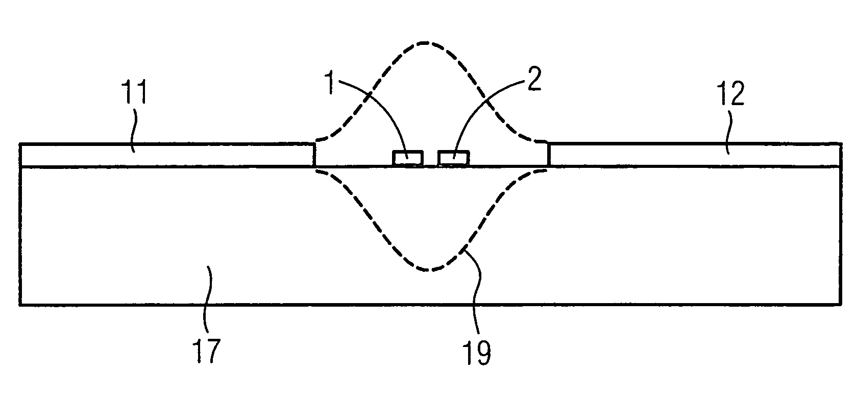
[0080]FIG. 2 shows, schematically, a bridge circuit for the apparatus according to the invention. As in FIG. 1, the bridge circuit shown in FIG. 2 has a first resistance element 1, a second resistance element 2, a third resistance element 3 and a fourth resistance element 4. This bridge circuit likewise has a first input terminal 5 and a second input terminal 6, as well as a first output terminal 7 and a second output terminal 8. The bridge circuit shown in FIG. 2 with regard to the electrical connection, is identical to the bridge circuit shown in FIG. 1. The bridge circuits in FIG. 1 and FIG. 2 differ only in the geometrical arrangement of the resistance elements 1, 2, 3 and 4.

[0081]The resistance elements 1, 2, 3 and 4 in FIG. 2 are aligned with their longitudinal directions parallel to one another. The resistance values of the resistance elements 1, 2, 3 and 4 in FIG. 2 also depend on the field strength of that component of the magnetic field which extends at right angles to the...


PUM


Abstract

An apparatus for detection of the gradient of a magnetic field includes at least four antenna elements (11, 12, 13, 14) composed of a ferromagnetic material, which are arranged in pairs, and a bridge circuit having at least four resistance elements (1, 2, 3, 4), which are associated with the antenna elements (11, 12, 13, 14) or antenna element pairs. Each antenna element pair has at least one associated resistance element (1, 2, 3, 4) whose resistance value is dependent on the field strength and on the direction of the magnetic field, and which resistance element (1, 2, 3, 4) is arranged in a field area (19) which extends between the two antenna elements (11, 12, 13, 14) of the antenna element pair. The invention also relates to a method for production of an apparatus which is intended for detection of the gradient of a magnetic field.

Description

FIELD OF THE INVENTION[0001]The invention relates to an apparatus for detection of the gradient of a magnetic field as claimed in patent claim 1. The invention also relates to a method for production of an apparatus, which is intended for detection of the gradient of a magnetic field, as claimed in the independent patent claims 20 and 32.BACKGROUND OF THE INVENTION[0002]Apparatuses with appropriately high resolution are required for detection of magnetic fields with a low field strength. Conventional apparatuses admittedly achieve the necessary resolution, but problems occur as soon as there are interfering electromagnetic fields in the vicinity.[0003]The required resolution is admittedly achieved by the use of SQUID sensors (SQUID=Superconduction Quantum Interference Device), but problems occur in the event of interference caused by electromagnetic fields in the vicinity. Furthermore, the SQUID sensors have antenna elements composed of superconducting material. These require coolin...

Claims


Application Information

Patent Timeline
IPC IPC(8): H01Q1/00H01Q1/38
CPCG01R33/022H01L27/22H10B61/00H10N59/00
Inventor DAALMANS, GABRIEL
Owner SENSITEC
Why Eureka
Try Eureka