Device capable of switching between an image display status and a mirror status, and an instrument disposed therewith

a technology of image display and mirror, which is applied in the direction of instruments, non-linear optics, optics, etc., can solve the problems of insufficient use of mirror-like states, difficult balance between and difficulty in balancing both bright image display and bright mirror. , to achieve the effect of improving the usability of illumination light and high

Inactive Publication Date: 2009-02-24
PANASONIC LIQUID CRYSTAL DISPLAY CO LTD +1
View PDF9 Cites 206 Cited by
  • Summary
  • Abstract
  • Description
  • Claims
  • Application Information

AI Technical Summary

Benefits of technology

[0013]It should be noted that the birefringence reflective polarization film, in which different birefringence polymer films are alternatingly laminated, disclosed in, for example, International Application International Publication No. WO95 / 27919 can be used as a reflective polarizing plate. This reflective polarizing plate is one that is ordinarily disposed between a lighting system (backlight) and a polarizing plate disposed at an undersurface side of a liquid crystal element and in which extremely high effects are obtained when used for the purpose of improving the usability of illumination light. However, because leakage of light with respect to a predetermined polarization becomes a large problem when realizing mirror capabilities of the kind that the present inventors aim to realize, sufficient mirror capabilities cannot be obtained only with this kind of reflective polarizing plate.
[0014]It is an object of the present invention to provide a device that is capable of switching between a state in which a high-quality image is displayed and a mirror status in which is obtained an easy-to-view reflection image suitable for a person to view his / her own face or figure.

Problems solved by technology

Although the above-described conventional display devices are capable of switching to a mirror-like state that reflects outside light, the mirror-like state is insufficient to use as a mirror with which a person can view his / her own reflected face or figure.
However, when the reflectance of the half mirror is raised, the display image becomes dark because the light amount of the image drops by the amount of light reflected by the half mirror material at the time the display device is in the image display status.
That is, because there is a trade-off relation between the brightness of the image in the image display status and the brightness of the mirror in the mirror status, it is difficult to balance both a bright image display and a bright mirror.
For this reason, it is difficult to raise the brightness of the mirror status of a display device using a half mirror to the extent that it can be used as a mirror for a person to view his / her own reflected face or figure.
For this reason, deterioration of image quality, such as glare of the outside light and a drop in the contrast ratio of the image resulting from reflection of the outside light, arises in the image display status.

Method used


Image

  • Device capable of switching between an image display status and a mirror status, and an instrument disposed therewith
  • Device capable of switching between an image display status and a mirror status, and an instrument disposed therewith
  • Device capable of switching between an image display status and a mirror status, and an instrument disposed therewith

Examples


first embodiment

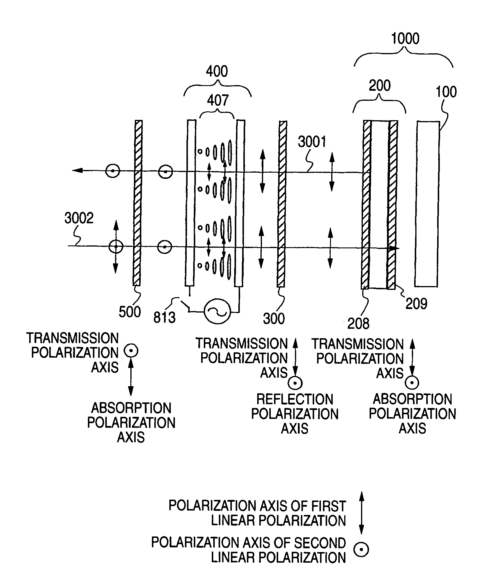
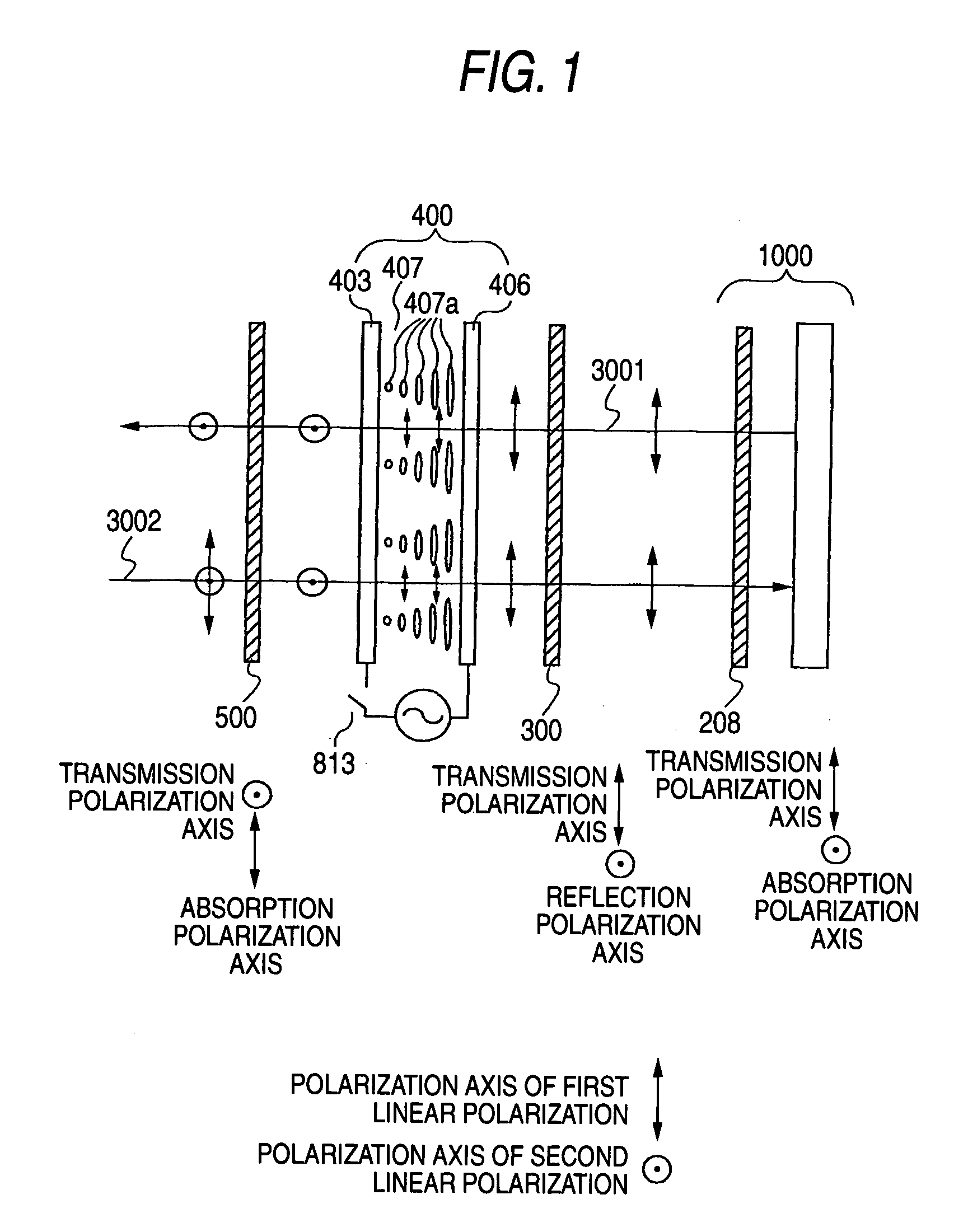
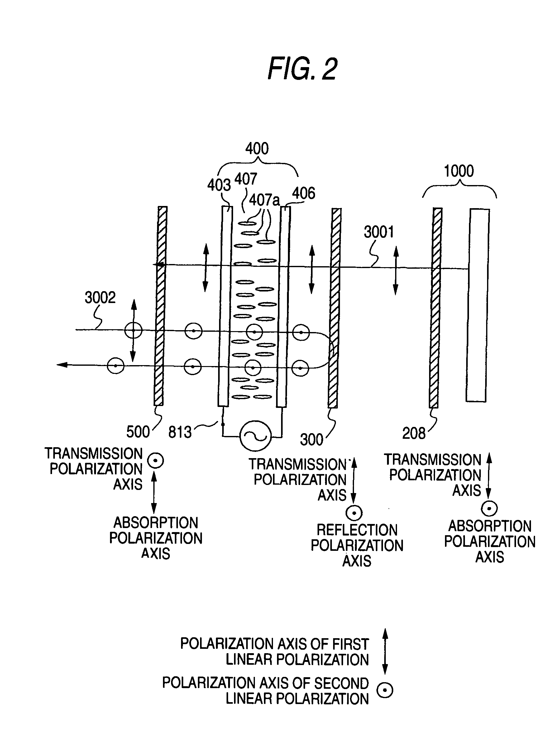
[0066]First, the basic configuration and operation of a display device disposed with a function for switching to a mirror status of a first embodiment will be described using FIGS. 1 and 2.

[0067]As shown in FIG. 1, the display device of the first embodiment includes an image display portion 1000, a reflective polarization selection member 300, a transmission polarization axis variable portion 400, and an absorbing polarization selection member 500, which are successively disposed. The image display portion 1000 includes an absorbing polarization selection member 208 that transmits a linear polarization component of a predetermined direction and absorbs a linear polarization component of a direction orthogonal thereto, and the absorbing polarization selection member 208 is disposed at the reflective polarization selection member 300 side. In the present embodiment, the image display portion 1000 includes two absorbing polarization selection members that sandwich a lighting system, a ...

second embodiment

[0090]Next, the basic configuration and operation of a display device disposed with a function for switching to a mirror status of a second embodiment of the invention will be described using FIGS. 5 and 6.

[0091]The display device of the second embodiment is one in which the absorbing polarization selection member 500 of the display device of FIGS. 1 and 2 of the first embodiment is replaced with a combination of a reflective polarization selection member 301 and a variable polarization selection member 600. Because other configurations are the same as those of the display device of the first embodiment, the same reference numerals will be given to the same parts and detailed description thereof will be omitted.

[0092]The reflective polarization selection member 301 is disposed at a position facing the transmission polarization axis variable portion 400, and the variable polarization selection member 600 is disposed further toward the viewer side than the reflective polarization sele...

example 1

[0120]A display device disposed with a function for switching to a mirror status of Example 1 of the invention will be described using FIGS. 7 and 8. The basic configuration of the display device of Example 1 is the same as that of the display device shown in FIGS. 1 and 2 of the first embodiment.

[0121]Similar to the first embodiment, the display device of FIG. 7 of Example 1 includes the image display portion 1000, the reflective polarization selection member 300, the transmission polarization axis variable portion 400, and the absorbing polarization selection member 500, which are successively superimposed. These are accommodated inside a case 1070 that includes an opening 1071. The opening 1071 serves as an image display portion capable of being switched to the mirror status. The action of each part is as was described in the first embodiment.

[0122]As shown in FIGS. 7 and 8, the image display portion 1000 includes a liquid crystal display panel 200, which includes a display-use l...


PUM

PropertyMeasurementUnit
sizeaaaaaaaaaa
sizeaaaaaaaaaa
reflectanceaaaaaaaaaa

Abstract

There is provided a device capable of switching between a state that displays a high-quality image and a mirror status in which is obtained an easy-to-view reflection image suitable for a person to view his/her own face or figure. An image display portion 1000 that emits image light 3001, reflective polarization selection means 300 that transmits a first linear polarization component emitted from the image display portion 1000 and reflects a second linear polarization component, whose polarization axis is orthogonal to that of the first linear polarization component, a transmission polarization axis variable portion 400 capable of selecting between one of a state that changes the polarization axis of incident linearly polarized light and a state that does not change the polarization axis of incident linearly polarized light, and a polarization selection member 500 which, of the incident light, absorbs the first linear polarization component and transmits the second linear polarization component, whose polarization axis is orthogonal to that of the first linear polarization component, are disposed in this order. In this case, absorbing polarization selection means 208 is disposed at the image display portion 1000, and the first linear polarization is emitted as the image light.

Description

TECHNICAL FIELD[0001]The present invention relates to a display device including a mirror function that can switch a display screen to a mirror, an instrument disposed therewith, and to a mirror including an image display function that can switch a mirror to an image display screen, and an instrument disposed therewith.BACKGROUND ART[0002]As described in, for example, JP-A-11-15392 and JP-A-11-291817, display devices in which a half mirror material is disposed on a front surface of an image display member, such as a liquid crystal display device, have been known as display devices capable of switching to a mirror status that reflects outside light (or a mirror disposed with a display function). In these display devices, because outside light reflected by the half mirror material becomes greater than image light transmitted through the half mirror material when a lighting system is turned off or when an image is a dark display, the state becomes a mirror status. Conversely, because t...

Claims


Application Information

Patent Timeline
Patent Type & Authority Patents(United States)
IPC IPC(8): G02F1/1335G02F1/13357G02F1/1347
CPCG02F1/133536G02F1/13362G02F1/1347G02F2203/62G02F1/13475G02F1/1335
Inventor ADACHI, MASAYATSUMURA, MAKOTOFUJI, GOROUTA
Owner PANASONIC LIQUID CRYSTAL DISPLAY CO LTD
Why Eureka
Try Eureka