
Internal voltage generator

a voltage generator and internal voltage technology, applied in the field of semiconductor memory devices, can solve the problems of large capacity and high operating speed, gate pattern failure, bit line precharge voltage leakage,

Inactive Publication Date: 2009-02-24
SK HYNIX INC
View PDF16 Cites 6 Cited by
  • Summary
  • Abstract
  • Description
  • Claims
  • Application Information

AI Technical Summary

Benefits of technology

[0022]It is, therefore, an object of the present invention to provide an internal voltage generator that can solve a leakage current problem caused by a bridge between a word line and a bit line in a power-down mode.
[0023]It is another aspect of the present invention to provide an internal voltage generator that can obtain a stable and reliable bit line precharge voltage when a power down mode is exited.

Problems solved by technology

In semiconductor memory devices, the biggest issue is the large capacity and high operating speed.
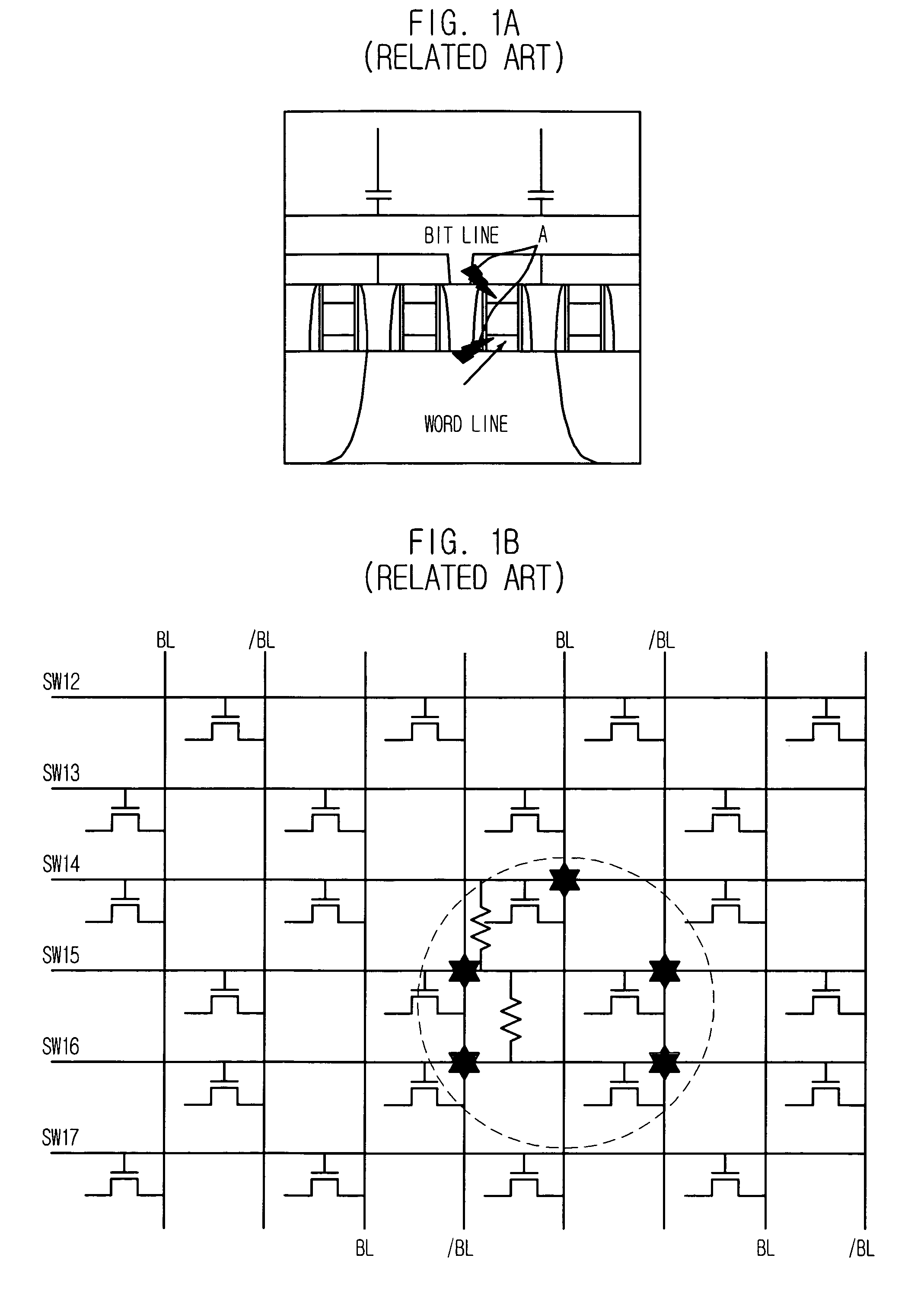
A gate residue occurs due to a manufacturing process problem when the word lines and the bit lines are formed, causing a bridge phenomenon.
One of the results of the bridge is a gate pattern failure.
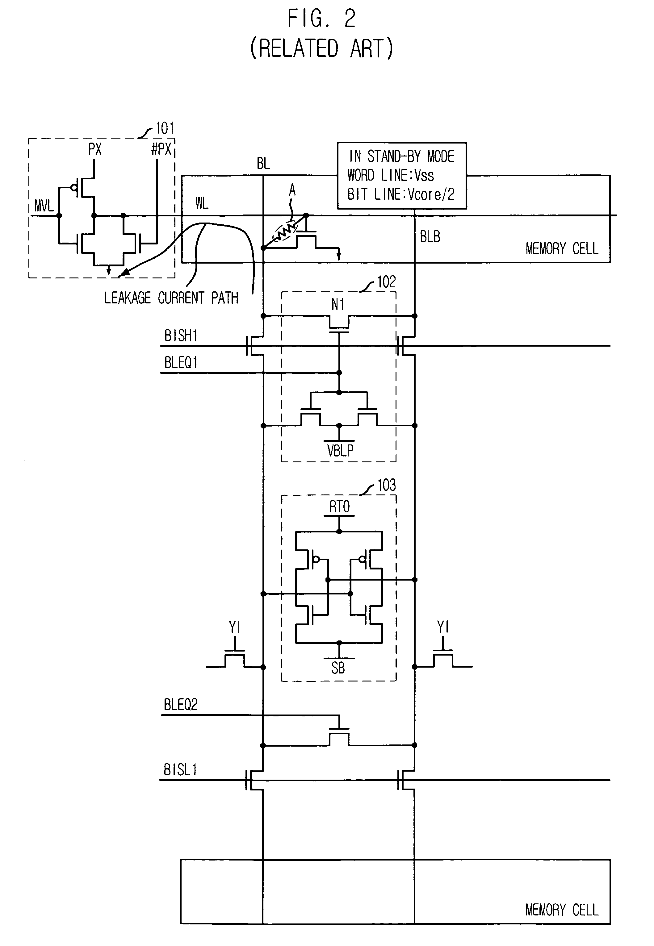
The resistive short causes a bit line precharge voltage to leak out during a bit line precharge operation.
Such a manufacturing process problem increases the power consumption of the semiconductor memory device, degrading the power efficiency and performance of products.
These leakage currents are a significant factor to decrease the yield because a low-power product has a 7-10% portion based on the stand-by current ISB versus 1 bridge.
However, since an amount of a leakage current is different according to the size of the gate pattern failure, it is difficult to solve the leakage current problem by using the conventional voltage drop transistor, a so-called bleeder.
That is, the conventional drop transistor cannot cope with the bridge having various resistances.

Method used


Image

  • Internal voltage generator
  • Internal voltage generator
  • Internal voltage generator

Examples


Embodiment Construction

[0034]An internal voltage generator in accordance with exemplary embodiments of the present invention will be described in detail with reference to the accompanying drawings.

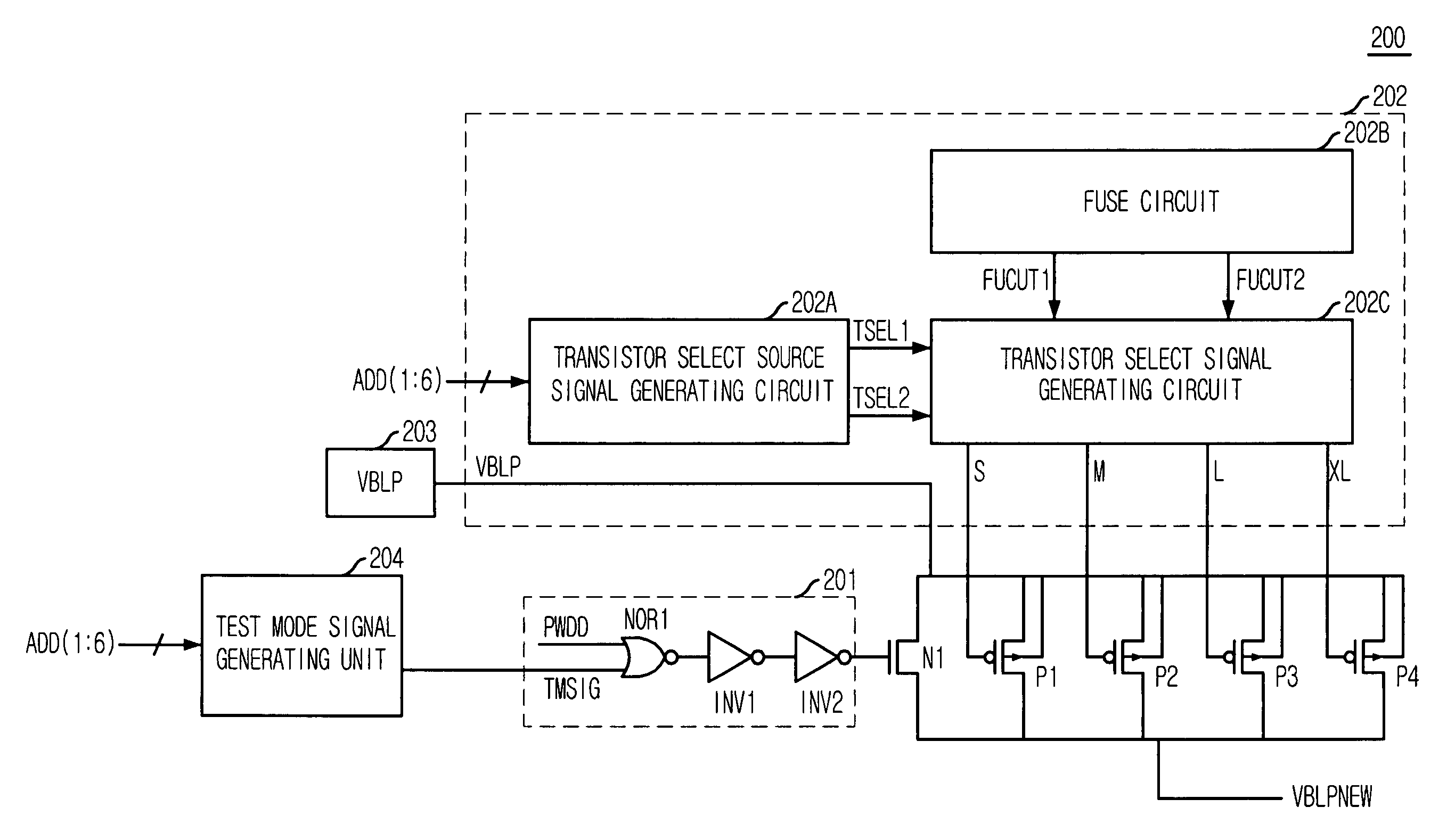
[0035]FIG. 4 is a circuit diagram of a bit line precharge voltage generator in accordance with an embodiment of the present invention.

[0036]The bit line precharge voltage generator 200 outputs a bit line precharge voltage VBLPNEW having different voltage levels according to a power down mode and a non power down mode.

[0037]The bit line precharge voltage generator 200 includes an NMOS transistor N1, a mode determining unit 201, a plurality of voltage drop transistors P1 to P4, a voltage drop transistor driving unit 202, and a precharge voltage generating unit 203. The NMOS transistor N1 outputs a bit line precharge voltage VBLPNEW in a normal mode, and the mode determining unit 201 determines a power down mode and a non power down mode in response to a power down mode signal PWDD and a test mode signal TMSIG. The...


PUM


Abstract

An internal voltage generator includes an output node, a bit line precharge voltage generating unit for generating a bit line precharge voltage, and a voltage drop block for dropping a voltage level of the bit line precharge voltage according to operating modes.

Description

FIELD OF THE INVENTION[0001]The present invention relates to a semiconductor memory device, and more particularly, to a bit line precharge voltage generator of a semiconductor memory device.DESCRIPTION OF RELATED ART[0002]In semiconductor memory devices, the biggest issue is the large capacity and high operating speed. In addition, many efforts have been made to develop semiconductor memory devices that can secure a reliable operation in a low power environment. Specifically, memory devices mounted on portable systems, e.g., mobile phones, notebook computers, etc., have been developed to minimize power consumption.[0003]One of these efforts is a technique to minimize power consumption in a core region of a memory device. The core region includes a memory cell, a bit line, and a word line and is designed based on an ultra-fine design rule. Therefore, the memory cell has a very small size and uses a low power.[0004]A bit line precharge is an important technique related to a cell data ...

Claims


Application Information

Patent Timeline
Patent Type & Authority Patents(United States)
IPC IPC(8): G11C7/00
CPCG11C5/14G11C7/12G11C2207/2227
Inventor PARK, SANG-IL
Owner SK HYNIX INC
Learn More