Hydraulic fluid tank for drilling machine

a technology of hydraulic fluid and drilling machine, which is applied in the direction of drilling pipes, mechanical equipment, rotary drilling, etc., can solve the problems of increasing the profile of the machine, affecting the efficiency of the machine, so as to achieve the effect of reducing interference with access, high center of mass of the machine, and increasing efficiency

Inactive Publication Date: 2009-03-03
ASTEC INDS
View PDF14 Cites 7 Cited by
  • Summary
  • Abstract
  • Description
  • Claims
  • Application Information

AI Technical Summary

Benefits of technology

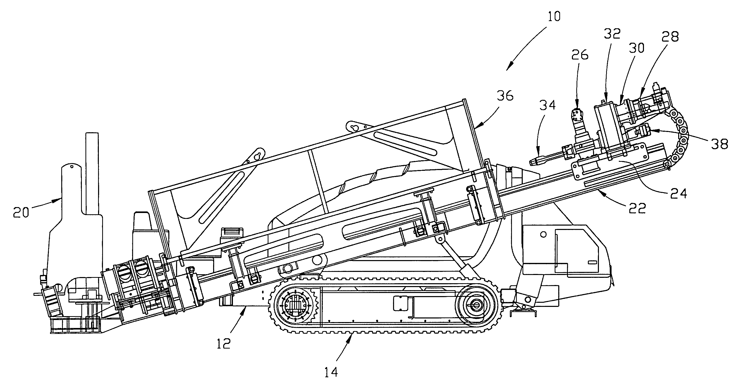
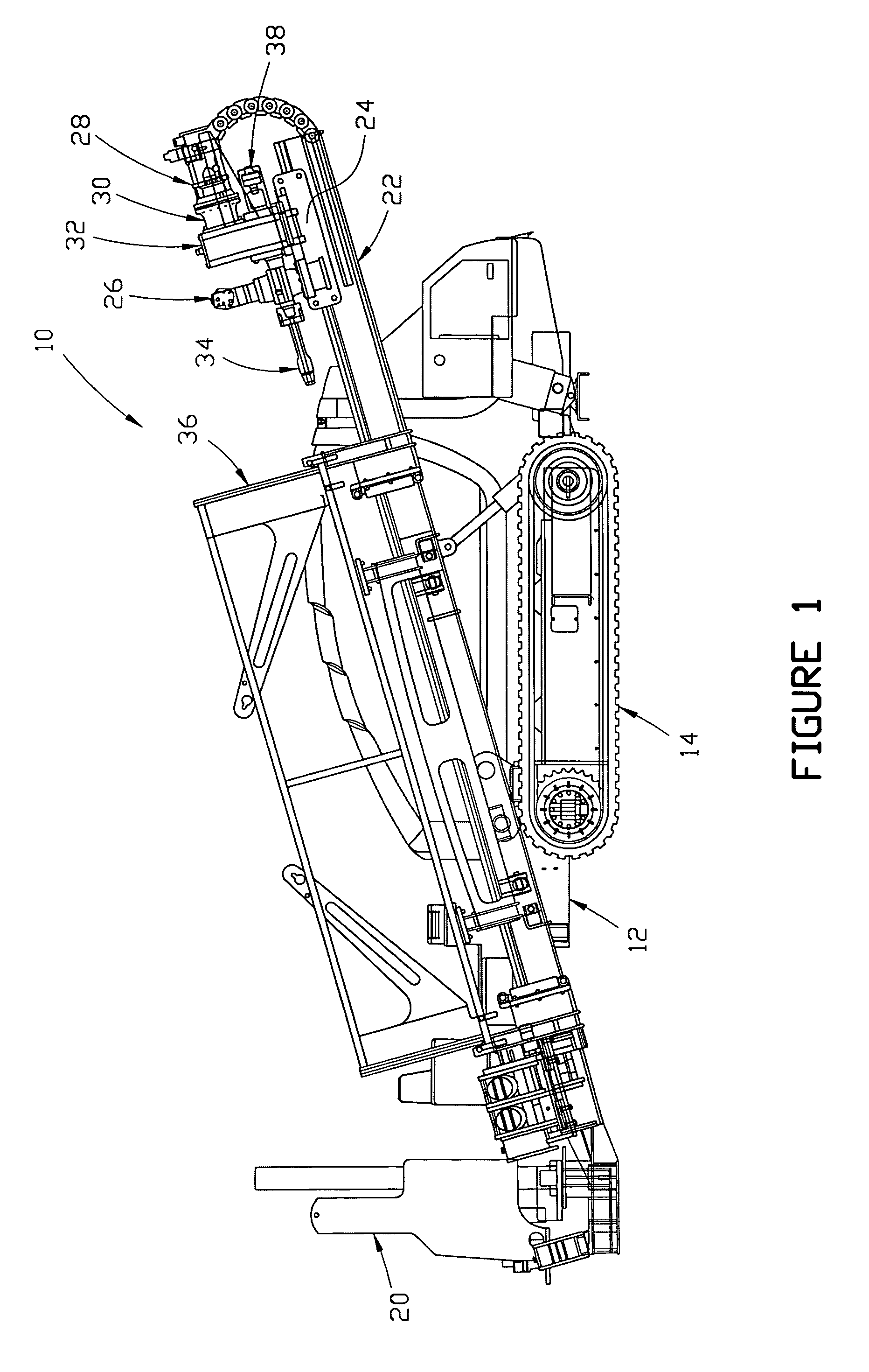
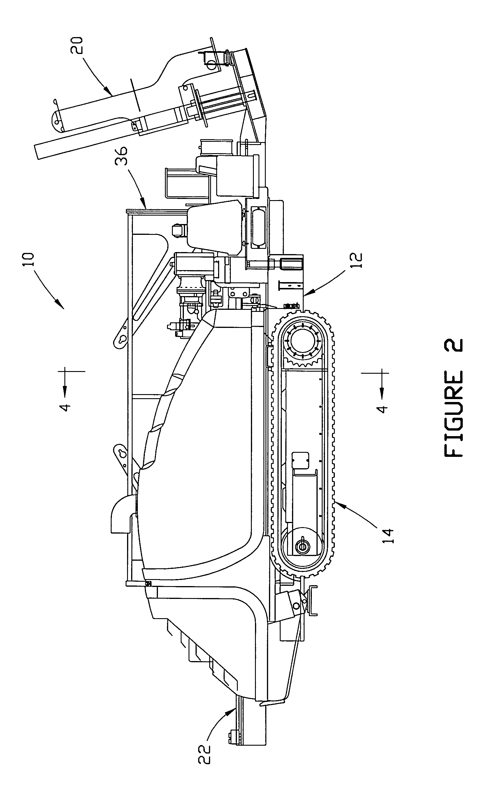
[0009]Among the advantages of a preferred embodiment of the invention is that it provides a hydraulic fluid tank for a drilling machine which minimizes interference with access to the hydraulic pumps and other components of the machine. Another advantage of a preferred embodiment of the invention is that it provides a tank which does not result in a high center of mass of the machine. Still another advantage of a preferred embodiment of the invention is that it provides a hydraulic fluid tank that is arranged and configured for increased efficiency due to thermal expansion of the hydraulic fluid.
[0010]Additional objects and advantages of this invention will become apparent from an examination of the drawings and the ensuing description.
[0011]The terms “above”, “upwardly” and similar terms, as used herein to indicate the position of a component of a hydraulic fluid tank or a drilling machine relative to another component, refer to a position higher in elevation when the tank or machine is in its normal operating configuration.
[0012]The terms “below”, “downwardly” and similar terms, as used herein to indicate the position of a component of a hydraulic fluid tank or a drilling machine relative to another component, refer to a position lower in elevation when the tank or machine is in its normal operating configuration.
[0013]As used herein, the “front” or “front end” of the drilling machine refers to the end on which the stakedown assembly is mounted.
[0014]As used herein, the “rear” or “rear end” of the drilling machine is the end opposite the front end.

Problems solved by technology

However, such constructions result in a high center of mass of the machine, which makes it somewhat unstable.
In addition, such constructions place the hydraulic fluid tank adjacent to the pump or pumps and / or the driving engine, thereby enlarging the machine's profile or making it difficult to access the pumps and / or engine for service.

Method used


Image

  • Hydraulic fluid tank for drilling machine
  • Hydraulic fluid tank for drilling machine
  • Hydraulic fluid tank for drilling machine

Examples


Embodiment Construction

[0009]Among the advantages of a preferred embodiment of the invention is that it provides a hydraulic fluid tank for a drilling machine which minimizes interference with access to the hydraulic pumps and other components of the machine. Another advantage of a preferred embodiment of the invention is that it provides a tank which does not result in a high center of mass of the machine. Still another advantage of a preferred embodiment of the invention is that it provides a hydraulic fluid tank that is arranged and configured for increased efficiency due to thermal expansion of the hydraulic fluid.

[0010]Additional objects and advantages of this invention will become apparent from an examination of the drawings and the ensuing description.

EXPLANATION OF TECHNICAL TERMS

[0011]The terms “above”, “upwardly” and similar terms, as used herein to indicate the position of a component of a hydraulic fluid tank or a drilling machine relative to another component, refer to a position higher in el...


PUM


Abstract

A hydraulic fluid tank for a drilling machine includes a primary chamber and a secondary chamber. The primary chamber is located entirely below the hydraulic pump of the drilling machine, and the secondary chamber is located above and in fluid communication with the primary chamber. The secondary chamber is adapted to maintain a hydraulic fluid level that is above the pump suction centerline of the drilling machine pump as the hydraulic fluid in the tank reaches its normal operating temperature during operation of the drilling machine. The secondary chamber is also sized and configured to allow for thermal expansion of hydraulic fluid in the amount of at least about 5% of the total tank volume as the hydraulic fluid in the tank reaches its normal operating temperature during operation of the drilling machine.

Description

FIELD OF THE INVENTION[0001]This invention relates generally to the hydraulic system of a drilling machine. More particularly, the invention relates to a hydraulic fluid tank for such a machine.BACKGROUND AND DESCRIPTION OF THE PRIOR ART[0002]Many utility lines, pipelines and other underground components are installed in or under the ground by boring a borehole in a generally-horizontal direction in the ground rather than by digging a trench. This type of construction, which is sometimes referred to as “horizontal boring”, “directional drilling” or “horizontal directional drilling”, eliminates the need to excavate earth in order to install an underground component, and thereby saves several steps in the installation process. If no trench is dug, there will be no trench to fill, and no disturbed surface to reclaim. The horizontal drilling machine may be operated to drill a pilot bore along a planned path underground. Typically, the planned path is generally arcuate in shape from the ...

Claims


Application Information

Patent Timeline
Patent Type & Authority Patents(United States)
IPC IPC(8): B23Q5/00
CPCE21B15/003E21B15/04F15B1/26
Inventor RANDALL, GUY P.BAKER, NEIL M.SHEPHERD, CHRISTOPHER L.
Owner ASTEC INDS
Why Eureka
Try Eureka