Grinding roller for the pressure comminution of granular material

a technology of grinding rollers and granular materials, which is applied in the field of grinding rollers, can solve the problems of limited wear resistance, high wear stress on the surface of the rollers, and high wear stress on the end faces of the rollers or the roller shells of the rolling presses, so as to facilitate the exchange of worn hard bodies, reduce wear stress, and improve the fit accuracy of hard bodies

Active Publication Date: 2009-03-03
KHD HUMBOLDT WEDAG GMBH
View PDF8 Cites 66 Cited by
  • Summary
  • Abstract
  • Description
  • Claims
  • Application Information

AI Technical Summary

Benefits of technology

[0007]The invention is based on the object of providing particularly the grinding rollers of high-pressure rolling mills or rolling presses for the pressure comminution of granular material not only with surface reinforcement but also with end-face reinforcement in the region of the peripheral edge of the rollers, which has a long service life as a result of high wear resistance and which can nevertheless be produced and repaired relatively easily and with low overall cost.
[0010]It is relatively easy to secure the hard bodies in the annular shoulder of the roller shell, so that the reinforcement can also be repaired by the operator of the rolling machine. According to one embodiment of the invention, the hard bodies may be clamped in the peripheral annular shoulder of the roller shell by means of screwing and wedging elements distributed over the periphery of the roller end face. The screw connections of the hard bodies with their annular shoulder may act axially and / or radially or obliquely diagonal. Instead of screwing the hard bodies onto the roller shell directly through corresponding bores by means of through-bolts, the hard bodies may also be clamped into the annular shoulder by means of clamping plates, which for their part are screwed onto the roller end face in a region lying radially more inward, where they are no longer exposed to wear.
[0011]The radially inner surfaces of the hard bodies in the form of segments of a circle, by which they are radially supported on the annular shoulder of the roller shell, may be adapted to the cylindrical contour of the annular shoulder by being arcuately curved in a convex manner. The radially inner hard body surface may, however, also be planar, in this case the radially inner contour of the annular shoulder representing a polygon. With a planar fit, even greater fitting accuracy of the hard bodies can be achieved.
[0012]According to one particular feature of the invention, the hard bodies may also have, seen in plan view, the shape of a hammerhead with a shaft, the hammerhead respectively being arranged in the annular groove of the roller shell and the shaft respectively being inserted in formed-in or milled-in radial / axial grooves distributed around the circumference of the roller end face. If the roller shell comprises a cast body, for example of chilled cast iron, there is the possibility of forming the annular shoulder and the radial / axial grooves in the roller shell already when it is cast, so that it is possible to dispense with machining operations.
[0013]According to another feature of the invention, the shaft of the hammerhead-shaped hard bodies may have at the end a cylindrical thickening, which is respectively made to fit in the radial bores of the outer series of bores adjacent the edge of the roller shell of the roller end face, so that the hard bodies are axially captured in the roller shell by this thickening, i.e. are secured in the axial direction against falling out, while the radial fixing of the hammerhead-shaped hard bodies can be achieved by them being adhesively bonded or soldered in their radial grooves. The adhesive bonding or soldering is intended to be reversible at low temperatures, to make it easier for worn hard bodies to be exchanged.

Problems solved by technology

The surfaces of the rollers thereby undergo a high level of wearing stress.
However, the end faces of the rollers or the roller shells of rolling presses are also subjected to high levels of wear, in particular when they are used for ore crushing.
Apart from the fact that it is questionable whether operators of such machines are capable of building up the wear protection themselves in the case of repair, the wear resistance is limited, because the welding technique cannot be used for applying very hard materials.
If these welded-on plates become worn in the course of operating the rolling press, material may be pressed into the radial gap between the end face of the roller and the wear plate and the wear plate forced out of its anchorage, so that the effort involved in maintaining this kind of wear protection for a grinding roller end face is considerable.

Method used


Image

  • Grinding roller for the pressure comminution of granular material
  • Grinding roller for the pressure comminution of granular material
  • Grinding roller for the pressure comminution of granular material

Examples


Embodiment Construction

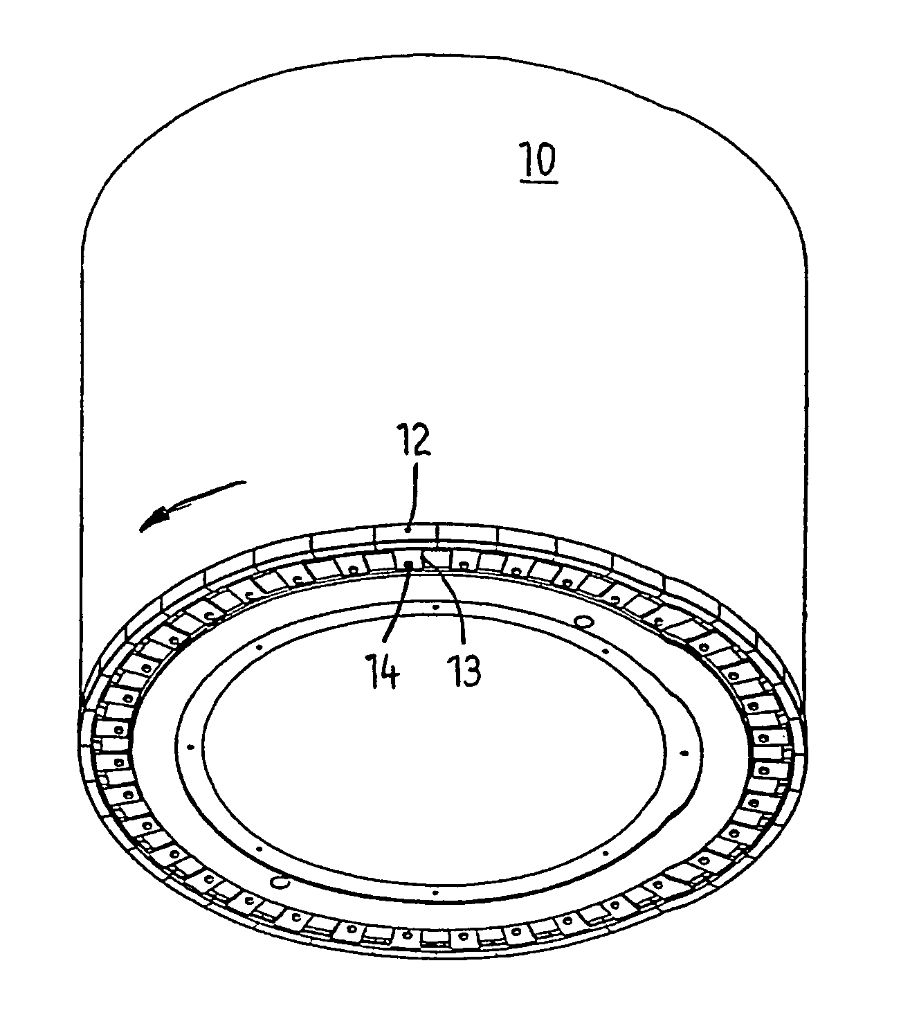
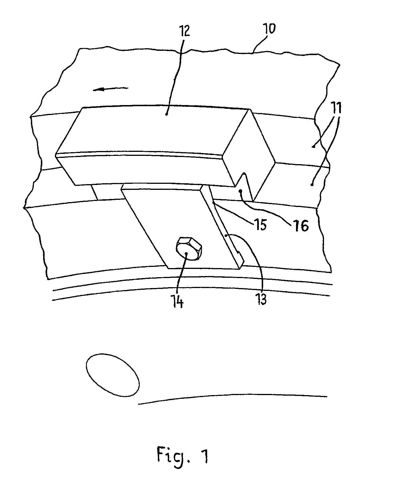
[0020]FIG. 1 shows, seen obliquely from above, the roller shell 10 of a grinding roller, on the end edge of which a peripheral annular shoulder 11 is integrally formed. Arranged in this annular shoulder are a multiplicity of prefabricated hard bodies, in particular of sintered hard metal, arranged in series to form a circle and forming the peripheral end edge of the roller, of which the inserted approximately right-parallelepipedal hard body 12 can be seen in FIG. 1, supported both axially and radially on the annular shoulder 11 of the roller shell 10 and detachably connected to it. The hard bodies 12 protrude both axially from the end face and radially from the surface of the roller shell 10, that is to say the height of the hard bodies 12 coincides with the surface reinforcement or grid armoring mentioned at the beginning, should this be present on the cylindrical surface of the roller shell 10 for the purpose of autogenous wear protection.

[0021]The radially inner surfaces of the ...


PUM


Abstract

The aim of the invention is to provide grinding rolls in particular for high-pressure roller mills or rolling presses for pressure grinding a granular material not only with a wear-resistant coating but also with a face armour plating in the area of the roller annular edge, which has a long service life due to the high wear resistance thereof and whose production and repair are, in general, relatively simple and inexpensive. For this purpose, the inventive face armour plating consists of a plurality of prefabricated hard bodies which are circularly arranged side by side in such a way that the circular face edge of the roller is formed, said hard bodies are disposed on said circular shoulder of a roll shell such that said hard bodies are placed axially and radially against said circular shoulder of the roll shell and are movably assembled with the roll shell.

Description

BACKGROUND OF THE INVENTION[0001]The invention relates to a grinding roller for the pressure comminution of granular material, in particular for rolling presses for comminuting a bed of material, having a roller shell with wear-resistant surface reinforcement, suitable in particular for autogenous wear protection, and with end-face reinforcement.[0002]In the case of rolling mills, granular, brittle material to be ground is drawn into the roller nip, by which the two rotatably mounted, counter-rotating rollers are separated from each other, and is subjected there to pressure comminution. Also known is so-called material-bed comminution in the roller nip of a high-pressure rolling mill, also known as a rolling press, in which the individual particles of the material to be ground that is drawn into the roller nip by friction are squeezed against one another in a bed of material, i.e. in a charge of material compressed between the two roller surfaces, when a high pressure is applied. Th...

Claims


Application Information

Patent Timeline
Patent Type & Authority Patents(United States)
IPC IPC(8): B02C4/30
CPCB02C4/30B02C4/305
Inventor SPLINTER, CHRISTIANFRANGENBERG, MEINHARDFISCHER-HELWIG, FRANKBRENDLER, DIETER
Owner KHD HUMBOLDT WEDAG GMBH
Why Eureka
Try Eureka