Dust extraction for power tools

a technology for power tools and dust extraction, applied in the direction of manufacturing tools, filtration separation, separation processes, etc., can solve the problems of reducing affecting the performance of dust extraction systems, and displacing this dust further. , to achieve the effect of improving performance, improving performance, and improving dust extraction performan

Active Publication Date: 2009-03-03
BLACK & DECKER INC
View PDF8 Cites 44 Cited by
  • Summary
  • Abstract
  • Description
  • Claims
  • Application Information

AI Technical Summary

Benefits of technology

[0013]These aforementioned aspects of the present invention are at least partially achieved by a dust collection chamber with a substantially circular cross section, the inlet to the dust collection chamber is at the perimeter of the circle and the outlet of the dust collection chamber is near the middle of the circle. With this arrangement, dust-laden air entering the dust collection chamber is caused to swirl around in a circular manner and forced against the outer wall of the dust collection chamber under the action of centrifugal force before air is exhausted from the dust collection chamber through the filter to atmosphere. Thus the air encountering the filter is less dust-laden than if the air encountered the filter directly. The throughput of air through the dust extraction system and the performance thereof are accordingly enhanced, and the filter is not subject to clogging as rapidly as existing systems.
[0028]The fan is preferably located on a drive shaft of a motor of the power tool, wherein the motor also provides the necessary power for the working head of the power tool, thereby remaining compact and lighter with respect to overall weight as the prior art systems. Moreover, the same drive shaft may carry a second fan operable to cool the motor. However, it is desirable that the second fan is preferably contained in a chamber of the power tool which is sealed from fluid communication with the duct forming part of the dust extraction system. This ensures that dust-laden air is not used to cool the motor.

Problems solved by technology

Vibrations associated with the operation of the power tools also tend to disperse this dust still further.
A working environment containing suspended dust is unpleasant, inconvenient and unhealthy for users of these tools.
Moreover, once the dust has settled, a user is required to clean-up and remove the scattered dust from the environment.
However, all of the prior art dust collection systems shown in U.S. Pat. Nos. 6,514,131, 6,224,471 and 4,967,516 and in FIGS. 2 to 4 below suffer from the disadvantage that the filters used therein easily become blocked with dust, thereby rapidly diminishing the performance of these dust extraction systems.
Moreover, unlike the dust extraction system discussed above in relation to FIG. 1, since the motor which powers the fan for transporting air through these dust extraction systems also provides motive power to the working head of the power tool, if the filters therein do become clogged with dust, the operation of the fan cannot be increased by a similar amount to compensate.

Method used


Image

  • Dust extraction for power tools
  • Dust extraction for power tools
  • Dust extraction for power tools

Examples


Embodiment Construction

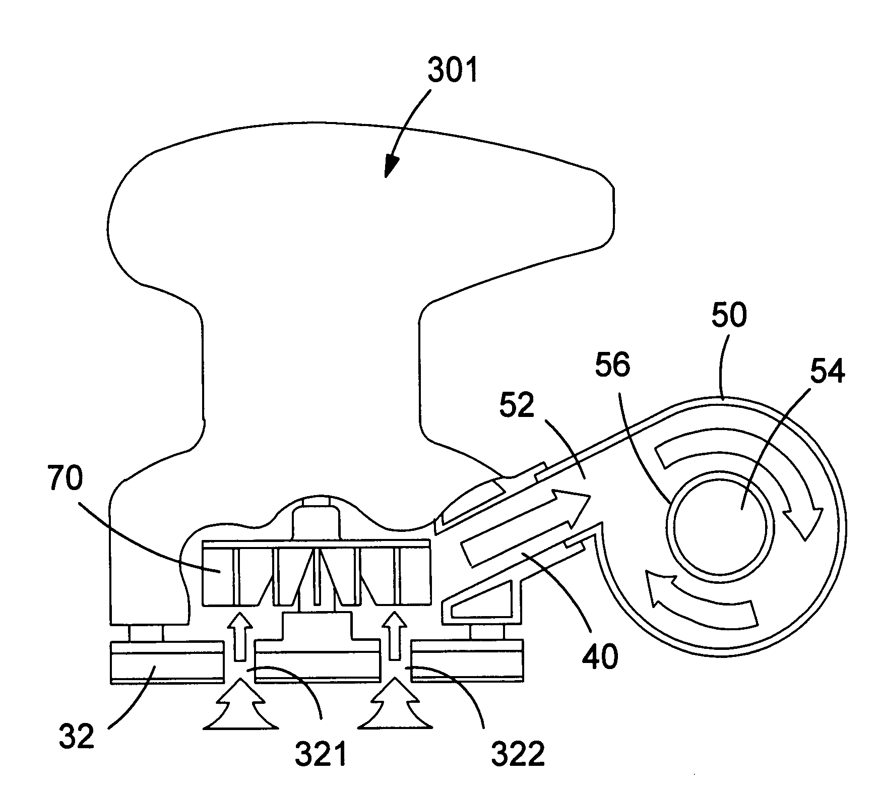
[0049]Referring to FIGS. 5 and 6, there is shown a power tool 30, which in this embodiment is a sander, having a working head 32, here a platten, for holding a working element, namely a sheet of sandpaper. A duct 40 has an inlet locatable in close proximity to the point of contact between the sheet of sandpaper and a workpiece by the provision of through-holes formed in the platten 32 in a conventional manner. A dust collection chamber 50 has an inlet 52 in fluid communication with an outlet from said duct, and an outlet 54 in fluid communication with atmospheric air. In this embodiment, the dust collection chamber 50 is substantially in the shape of a cylinder having a longitudinal axis oriented substantially horizontally with respect to the power tool, the inlet 52 to the dust collection chamber is located on the curved surface of the cylinder, and the outlet 54 of the dust collection chamber is located on an end face of the cylinder.

[0050]FIG. 7 shows an exploded view of the same...


PUM

PropertyMeasurementUnit
perimeteraaaaaaaaaa
cross-sectional areaaaaaaaaaaa
areaaaaaaaaaaa

Abstract

There is also provided a dust extraction module for use with a power tool, the dust extraction module having: a dust collection chamber (50) having an inlet (52) connectable in fluid communication with an outlet (44) of a dust-extracting duct (40) of the power tool, and having an outlet (54) in fluid communication with atmospheric air; and a filter (60) locatable in fluid flow between the outlet of the dust collection chamber and the atmospheric air; wherein the dust collection chamber (50) has a substantially circular cross section, the inlet (52) to the dust collection chamber is at the perimeter of the circle and the outlet (54) of the dust collection chamber is from the middle of the circle.

Description

FIELD OF THE INVENTION[0001]The present invention relates to dust extraction for power tools. More particularly, dust extraction for power tools of the hand-holdable variety, such as sanders, drills, routers, saws, hammers, grinders and other power tools generating sawdust when applied to a work piece.BACKGROUND OF THE INVENTION[0002]The dust generated by the use of power tools is of a fine particulate nature and floats easily in the surrounding air under normal operating conditions. Vibrations associated with the operation of the power tools also tend to disperse this dust still further. A working environment containing suspended dust is unpleasant, inconvenient and unhealthy for users of these tools. Moreover, once the dust has settled, a user is required to clean-up and remove the scattered dust from the environment. In view of these problems, a number of prior art arrangements have already been developed for extracting dust from around the operating region of power tools.[0003]E...

Claims


Application Information

Patent Timeline
Patent Type & Authority Patents(United States)
IPC IPC(8): B24B23/00B24B23/04
CPCB04C5/187B23Q11/0046B23Q11/0071
Inventor WALKER, ANDREW
Owner BLACK & DECKER INC
Why Eureka
Try Eureka