Check patentability & draft patents in minutes with Patsnap Eureka AI!

Method and system for establishing a communications connection

a communication connection and communication technology, applied in the field of communication, can solve the problems of increasing the complexity of the interoperability problem, the difficulty of overcoming the interoperability challenge, and the cost and time-consuming process of working through the interoperability challenge, so as to improve the quality of communication connections, reduce the production cost of a digital subscriber line access multiplexer, and enhance the interoperability

Inactive Publication Date: 2009-03-03
CISCO TECH INC
View PDF17 Cites 8 Cited by
  • Summary
  • Abstract
  • Description
  • Claims
  • Application Information

AI Technical Summary

Benefits of technology

[0005]Some embodiments of the invention provide numerous technical advantages. Other embodiments may utilize some, none, or all of these advantages. For example, according to one embodiment, interoperability is enhanced between communications devices by cycling through different parameters to determine that a parameter or set of parameters results in an optimal communications connection. According to another embodiment, the production cost of a digital subscriber line access multiplexer is reduced. According to another embodiment, the quality of communications connections is improved.

Problems solved by technology

Thus, interoperability between the numerous types of DSL equipment may become a challenge.
Working through the interoperability challenge is an expensive and time consuming process for a manufacturer of a digital subscriber line access multiplexer (“DSLAM”), which functions as a bridge between customer-side DSL equipment and the network.
The problem of interoperability may become more complicated when some customer-side DSL equipment manufacturers attempt to cut their production costs by sacrificing interoperability.
These cost-saving tactics may result in connections having poor quality or failed connections, which may be detrimental to consumers.

Method used


Image

  • Method and system for establishing a communications connection
  • Method and system for establishing a communications connection
  • Method and system for establishing a communications connection

Examples


Embodiment Construction

[0013]Embodiments of the invention are best understood by referring to FIGS. 1 through 4 of the drawings, like numerals being used for like and corresponding parts of the various drawings.

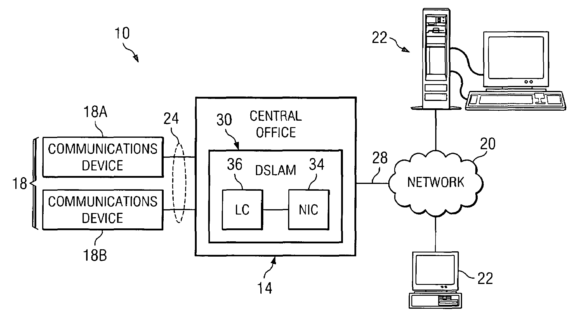
[0014]FIG. 1 is a schematic diagram of a communication system 10 that may benefit from the teachings of the present invention. System 10 includes a central office 14, one or more communication devices 18A and 18B (jointly referred to as communications devices 18), a network 20, such as an internet protocol network, and a plurality of communications devices 22. Devices 18 are coupled to central office 14 by physical lines 24, such as telephone lines. Central office 14 is coupled to network 20 by a trunk line 28. Trunk line 28 may be any suitable communications link that may carry internet protocol traffic, including OC3, DS3, and T1 (STM1, E3, E1, in Europe). Network 20 is coupled to communication devices 22, such as a server 22 having web site content. Network 20 and central office 14 allow communi...


PUM


Abstract

According to one embodiment of the invention, a method for establishing a communications connection is provided. The method includes transmitting, by a digital subscriber line access multiplexer to a communications device, a plurality of parameters each representing a different indication of a same feature of the digital subscriber line access multiplexer. Each parameter is correlated with one or more communications settings. The method also includes establishing a plurality of digital subscriber line connections with the communications device. Each connection corresponds with a particular one of the parameters. The method also includes selecting one of the connections as meeting a predetermined criteria. The method also includes identifying one of the parameters that corresponds to the selected connection. The method also includes establishing a digital subscriber line connection with the communications device using at least one communications setting correlated with the identified parameter.

Description

TECHNICAL FIELD OF THE INVENTION[0001]This invention relates generally to communications and more particularly to a method and system for establishing a communications connection.BACKGROUND OF THE INVENTION[0002]Digital subscriber line (“DSL”) technology is often employed in today's society to access the internet or other networks. In response to a growing popularity of DSL, many different communications equipment manufacturers are entering the DSL equipment market. As the number of such manufacturers increases, the diversity of DSL equipment also increases. Thus, interoperability between the numerous types of DSL equipment may become a challenge.[0003]Working through the interoperability challenge is an expensive and time consuming process for a manufacturer of a digital subscriber line access multiplexer (“DSLAM”), which functions as a bridge between customer-side DSL equipment and the network. For every new type of customer-side DSL equipment that enters the market, the DSLAM man...

Claims


Application Information

Patent Timeline
Patent Type & Authority Patents(United States)
IPC IPC(8): H04L12/28
CPCH04L12/2856H04L12/2883
Inventor BLACK, ROBERT B.
Owner CISCO TECH INC
Features
  • R&D
  • Intellectual Property
  • Life Sciences
  • Materials
  • Tech Scout
  • Unparalleled Data Quality
  • Higher Quality Content
  • 60% Fewer Hallucinations
Learn More