
Systems and methods for managing and analyzing faults in computer networks

a computer network and fault technology, applied in the field of systems and methods for managing and analyzing faults in computer networks, can solve the problems of wans, lans, vpns, vlans, increasing the number and complexity of communication networks, formation of loops, etc., and achieves the effect of facilitating root cause isolation and fault resolution and re-evaluation

Inactive Publication Date: 2009-03-03
COMP ASSOC THINK INC
View PDF108 Cites 69 Cited by
  • Summary
  • Abstract
  • Description
  • Claims
  • Application Information

AI Technical Summary

Benefits of technology

[0040]Advantageously, the present system creates a fault hierarchy or tree as a result of diagnosis of a single detected problem in a managed system and this facilitates root cause isolation. The fault tree facilitates a log of the entire diagnosis process for the analyzed fault, and inferred impact calculation based on the association of faults in the tree. The fault tree also facilitates fault resolution and re-evaluation because the conditions tested during the original diagnosis of a problem are recorded in the tree, and the ability to control the processing of faults based on fault state transition.

Problems solved by technology

A peripheral router connects a network to a larger internetwork, and thus may be limited to a single protocol.
In general, the use of WANs, LANS, VPNs, and VLANs has increased the number and complexity of communications networks.
Furthermore, most networks have redundant communication paths to prevent portions of the network from being isolated due to link failures.
However, redundant paths can also introduce problems such as formation of loops.
Furthermore, network performance can degrade due to improper network configurations, inefficient or incorrect routing, redundant network traffic or other problems.
Network hardware and software systems may also contain design flaws that affect network performance or limit access by users to certain of the resources on the network.
These factors make network management complex and difficult.
Network entities may send SNMP traps to the network management station when a problem in the network or network entity occurs.
Frequently, however, loss of contact information in an NMS database does not sufficiently represent various problems a network element can experience as a result of a fault in a communications network.

Method used


Image

  • Systems and methods for managing and analyzing faults in computer networks
  • Systems and methods for managing and analyzing faults in computer networks
  • Systems and methods for managing and analyzing faults in computer networks

Examples


Embodiment Construction

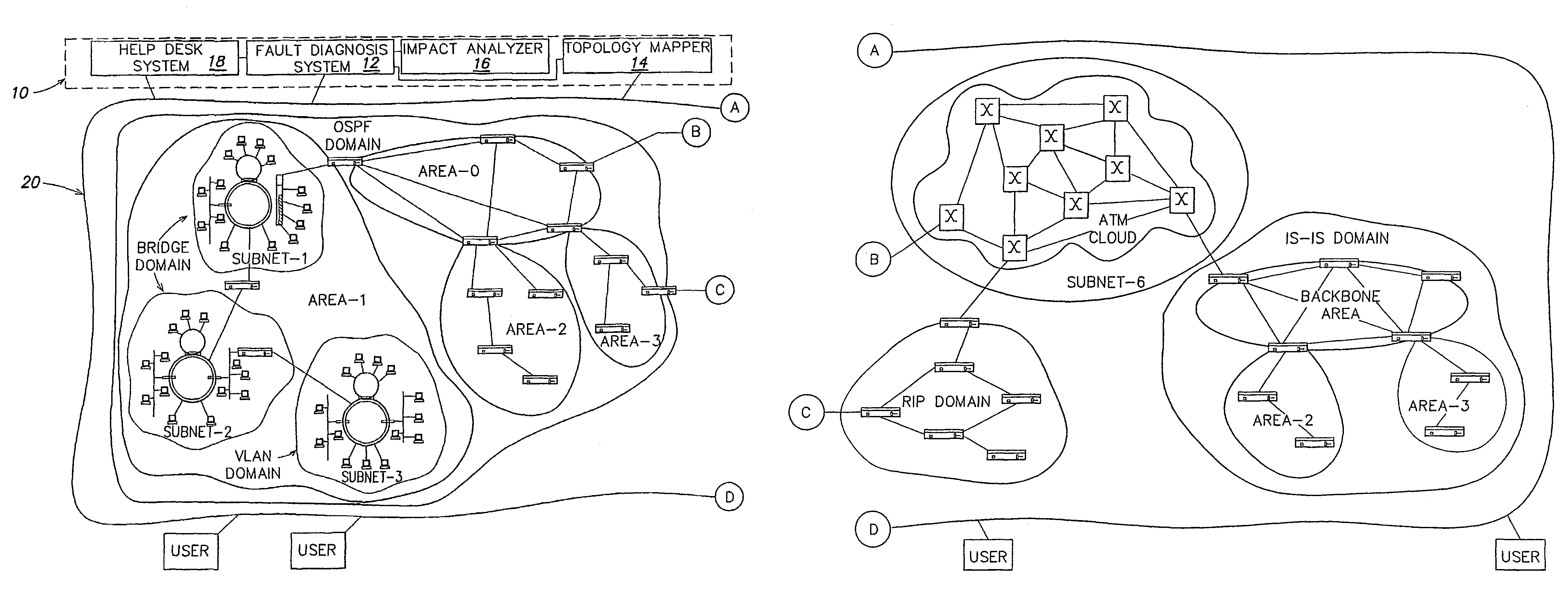
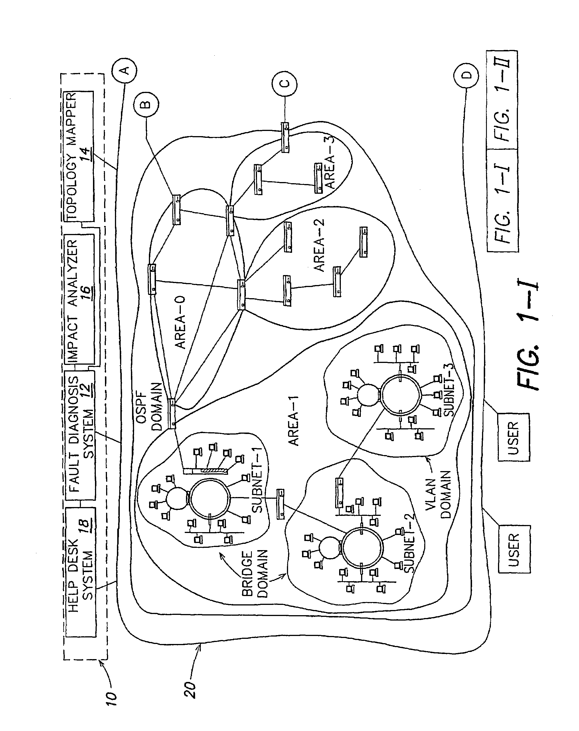
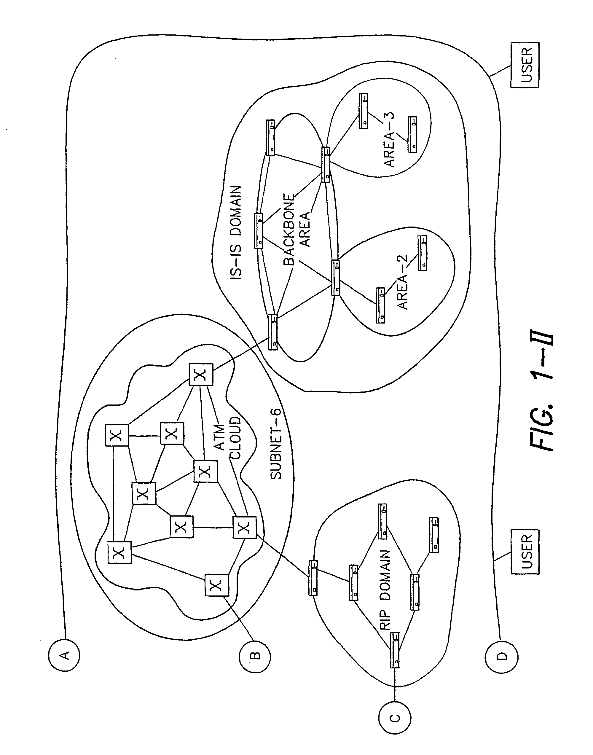
[0053]FIG. 1 shows diagrammatically a network management system 10 including a fault diagnosis system 12, a topology mapper 14, an impact analyzer 16 and a help desk system 18. The network management system communicates with a communications network 20 (or application service). The network includes a set of interconnected network elements such as routers, bridges, switches, and repeaters. These network elements provide transportation of data between end stations. Furthermore, there are computers known as servers that provide services such as e-mail, accounting software, sales tools, etc. Typically, data is transmitted electronically or optically, and network elements can forward data in packets, frames or cells to the intended destination. Servers include network adapters and / or software that interpret the electronic or optical data packet into the data elements and pass these elements to the appropriate application being hosted.

[0054]The network management system 10 includes a comm...


PUM


Abstract

A system (100) for analyzing a fault includes a fault object factory (110) constructed and arranged to receive fault data and create a fault object (112), and a fault diagnosis engine (101) constructed and arranged to perform root cause analysis of the fault object. The system may further include a fault detector (130) constructed and arranged to detect the fault data in a monitored entity, a fault repository (140) constructed and arranged to store and access the fault object; and a fault handler (150) constructed and arranged to be triggered by the fault diagnosis engine to analyze the fault object.

Description

[0001]This application claims priority from U.S. Provisional Application 60 / 202,296, entitled “Construction of a Very Rich, Multi-layer Topological Model of a Computer Network for Purposes of Fault Diagnosis,” filed on May 5, 2000, and claims priority from U.S. Provisional Application 60 / 202,299, entitled “A method for diagnosing faults in large multilayered environments guided by path and dependency analysis of the modeled system,” filed on May 5, 2000, and claims priority from U.S. Provisional Application 60 / 202,298, filed on May 5, 2000, entitled “Method and apparatus for performing integrated computer network, system, and application fault management,” all of which are incorporated by reference in their entireties.GENERAL DESCRIPTION[0002]The present invention relates a fault management and diagnosis system with a generic, easily extensible architecture.[0003]The construction of computer networks started on a large scale in the 1970's. Computer networks link personal computers, ...

Claims


Application Information

Patent Timeline
IPC IPC(8): G06F11/00
CPCH04L12/66
Inventor BUIA, CHRISTOPHER A.PANTELIS, THOMAS S.TAYLOR, DAVID K.BALL, SCOTTROCKWELL, NATHANIEL J.
Owner COMP ASSOC THINK INC
Learn More