Method for recording images of a definable region of an examination object using a computed tomography facility

a computed tomography and imaging facility technology, applied in the direction of radiation beam directing means, instruments, applications, etc., can solve the problems of reducing the measurement field, reducing the radiation load of the examination object in the region away from the defined reducing the radiation load of the examination object in the region of actual interest, so as to achieve the effect of low dose load for the patien

Inactive Publication Date: 2009-03-10
SIEMENS HEALTHCARE GMBH
View PDF9 Cites 21 Cited by
  • Summary
  • Abstract
  • Description
  • Claims
  • Application Information

AI Technical Summary

Benefits of technology

[0012]After the second isocenter has been determined, the image recording facility is then automatically repositioned in respect of the second isocenter; thus it is positioned so that it rotates about precisely this isocenter in the context of a subsequent recording. The invention makes use here of the fact that in the meantime computed tomography facilities have become known, which in principle allow relative movement of the image recording facility in relation to the examination object, which is lying in a fixed position on a patient support. Such a computed tomography facility in the form of a C-arm x-ray facility with a rotating C-arm is known for example from DE 199 58 864 A1. The C-arm is disposed on a support frame in the manner of a robot arm, being disposed on said support frame in such a manner that it can be rotated about a horizontal axis. Said support frame in principle allows variation of the position of the C-arm and therefore the image recording facility on the C-arm in relation to the patient support. This relative movement is utilized by the inventive method, wherein the image recording facility is now positioned precisely in such a manner that the axis of rotation of the image recording facility, therefore the horizontal axis of rotation of the C-arm, lies precisely in the second isocenter, which passes through the defined region.
[0015]The inventive method permits the recording of a region of interest, in other words a defined three-dimensional volume of interest in a very simple manner, in conjunction with a significantly lower radiation load for the patient due to the inventive repositioning of the image recording facility in respect of a second isocenter and the inventive tailoring of the measuring field. If recording is carried out with the same radiation dose as in the context of the first recording with a large measuring field, the radiation load must be smaller, since the object regions away from the region of interest within the isocenter are only exposed to direct radiation to a minor degree, in contrast to the large, maximum measuring field. If a high or the highest possible dose is used in the context of the second recording, the radiation load is also significantly smaller for this reason, compared with a high-dose image recording with the significantly larger measuring field according to the prior art with just one isocenter.
[0026]In general the inventive method allows high-speed recording of a low-resolution overview image recorded with a low dose with a large measuring field, followed by the maximum-resolution recording of any small region of interest with a minimal measuring field and any high, even the maximum dose without having to move the patient due to the capacity of the image recording facility to be moved to allow rotation about a second isocenter. This allows any structures in the overview image to be displayed at high speed with maximum resolution, for example organs or bone structures or even implants, such as an inserted stent, etc. The radiation load for the patient is minimal however.

Problems solved by technology

However since the image recording facility also rotates about the same isocenter during the second recording, the measuring field reduction is limited, as it must be ensured that the measuring field captures the region of interest in every instance from any recording direction.
As a result the radiation load on the examination object in regions away from the defined region of actual interest is considerably high due to the necessarily relatively large measuring field during this second scan.
Also the recorded image data set per individual image is considerably large due to the large measuring field.

Method used


Image

  • Method for recording images of a definable region of an examination object using a computed tomography facility
  • Method for recording images of a definable region of an examination object using a computed tomography facility
  • Method for recording images of a definable region of an examination object using a computed tomography facility

Examples


Embodiment Construction

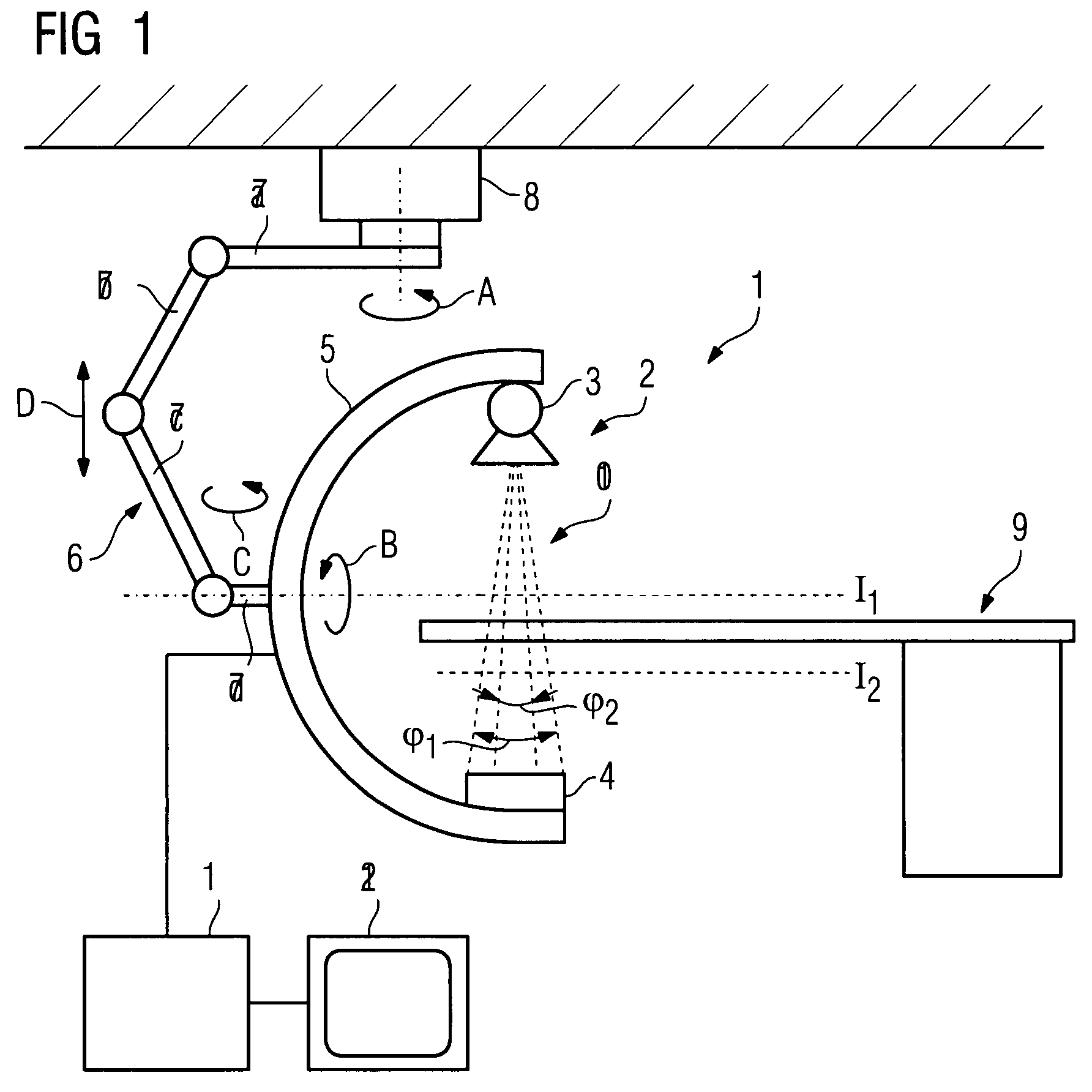
[0031]FIG. 1 shows a computed tomography facility 1, comprising an image recording facility 2, comprising a radiation source 3 and a radiation detector 4, for example in the form of a solid detector. The radiation source 3 and radiation detector 4 are disposed on a C-arm 5, which is in turn disposed on a support arm structure 6 in the manner of a robot arm, which in the example shown consists of four arms 7a, 7b, 7c and 7d, which are linked to each other by way of corresponding joints. The arm 7a is disposed on a ceiling-side support 8, on which it is disposed in such a manner that it can be rotated about a first axis of rotation, shown by the arrow A. The C-arm is disposed on the support arm 7d in such a manner that it can be rotated about a horizontal axis B, in order to be able to record computed tomography images by rotating the image recording facility 2, and it can also be pivoted as required about a vertical axis, as shown by the arrow C. The support arm structure 6 allows a ...


PUM


Abstract

There is described a method for recording images of a definable region of an examination object using an x-ray diagnostics facility for producing computed tomography recordings comprising an image recording facility comprising at least one radiation source and at least one radiation detector for the rotating recording of individual images, on the basis of which an image suitable for outputting is produced, comprising the following steps: Recording of images of the entire examination region by rotating the image recording facility about a first isocenter with a first measuring field, a first resolution and a first dose, and generating an overview image of the examination object; Defining the region in the examination object based on the overview image and defining the location of a second isocenter as a function of the location and / or geometry of the region.

Description

CROSS REFERENCE TO RELATED APPLICATIONS[0001]This application claims priority of German application No. 10 2006 044 783.2 DE filed Sep. 22, 2006, which is incorporated by reference herein in its entirety.FIELD OF INVENTION[0002]The invention relates to a method for recording images of a definable region of an examination object using an x-ray diagnostics facility for producing computed tomography recordings, a computed tomography facility, comprising an image recording facility comprising at least one radiation source and at least one radiation detector for the rotating recording of individual images, on the basis of which an image suitable for outputting is produced.BACKGROUND OF INVENTION[0003]It is known that it is possible with a computed tomography facility, due to the rotation of the image recording facility, to record a plurality of individual images of the examination object from different directions. These individual images are then processed using an image processing facil...

Claims


Application Information

Patent Timeline
Patent Type & Authority Patents(United States)
IPC IPC(8): H05G1/02
CPCA61B6/032A61B6/4441A61B6/4464A61B6/4458A61B6/469A61B6/488A61B6/463
Inventor KALENDER, WILLI
Owner SIEMENS HEALTHCARE GMBH
Why Eureka
Try Eureka