High-pressure/high-temperature seals between glass fibers and metals, downhole optical feedthroughs containing the same, and methods of preparing such seals

a technology of glass fibers and metals, which is applied in the direction of optical fibers with multi-layer cores/claddings, optical waveguide light guides, instruments, etc., can solve the problems of affecting the performance of the optical fiber, the inner surface of the borehole is often rough, and the optical fiber is particularly vulnerable to environmental stresses and contamination. , to achieve the effect of high strength, high strength and high strength

Active Publication Date: 2009-03-10
GREENE TWEED TECH
View PDF35 Cites 12 Cited by
  • Summary
  • Abstract
  • Description
  • Claims
  • Application Information

AI Technical Summary

Problems solved by technology

Optical fiber can be particularly vulnerable to environmental stresses and contamination.
Drilled wells can be extremely aggressive environments.
The inner surface of boreholes tends to be very rough, and in addition, drilling muds, which are used to facilitate drilling, contain chemical additives which can degrade non-metallic materials.
Furthermore, other fluids that may be present in a borehole can include saltwater, crude oil, carbon dioxide, hydrogen sulfide and others, many of which are highly corrosive to a wide variety of materials.
Downhole conditions become progressively more hostile and aggressive as the depth of the bore increases.
Such downhole conditions, including high pressure, high temperature and corrosiveness, can easily damage external or exposed downhole tool components.
In addition, any such seals, fittings, etc. must not create stress on the optical fiber.
Such external stress on an optical fiber can lead to improper transmission of the optical signal and / or physical failure of the fiber.

Method used


Image

  • High-pressure/high-temperature seals between glass fibers and metals, downhole optical feedthroughs containing the same, and methods of preparing such seals
  • High-pressure/high-temperature seals between glass fibers and metals, downhole optical feedthroughs containing the same, and methods of preparing such seals

Examples


Embodiment Construction

[0020]Reference will now be made in detail to the invention and the presently described embodiments thereof, examples of which are illustrated in the accompanying drawings. Although the disclosure herein refers to certain illustrated embodiments, it is to be understood that these embodiments are presented by way of example and not by way of limitation.

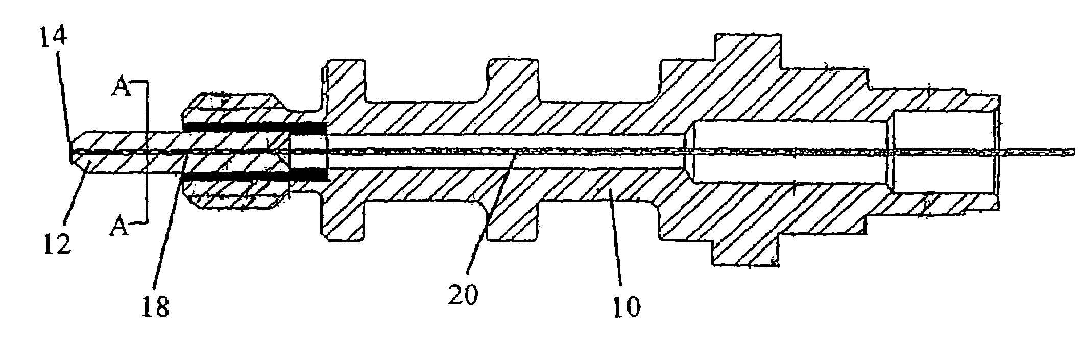
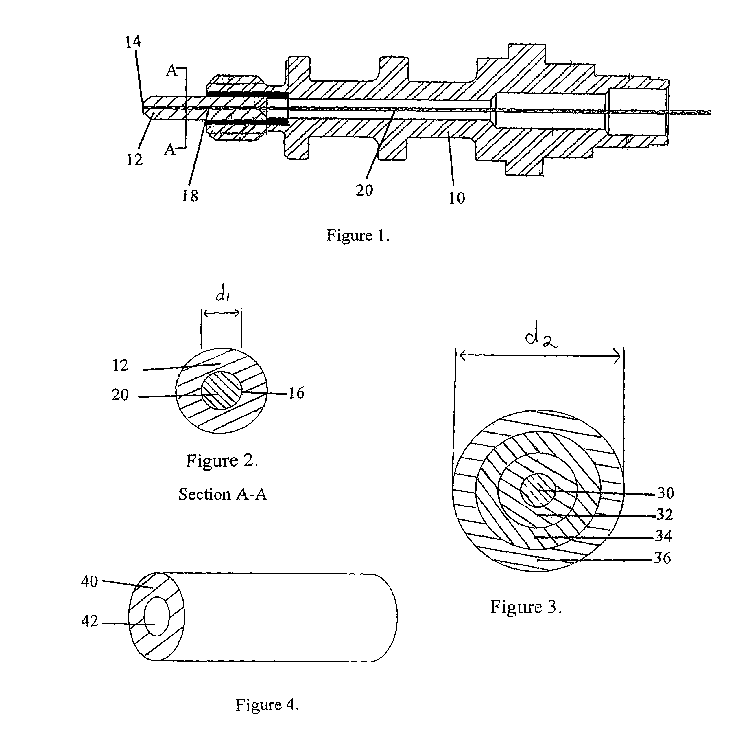
[0021]In an embodiment of the present invention, as shown in FIG. 1, a feedthrough housing 10 is configured to house an object 12. The object 12 has a bore 14 that extends through the object and can be coaxial with the feedthrough housing 10. As shown in FIG. 2, the object 12 has an inner surface 16 that defines the bore 14. The overall size or dimension of the bore (e.g., diameter d1 when the bore is circular as shown in FIG. 2) is typically greater than an outer dimension of the metallized portion 18 of the glass fiber 20 (i.e., diameter d2 of the metallized portion of the glass fiber as shown in FIG. 3). The object 12 can be of any ...


PUM

PropertyMeasurementUnit
melting temperatureaaaaaaaaaa
thicknessaaaaaaaaaa
thicknessaaaaaaaaaa

Abstract

A glass-to-meal seal for use in high temperature and high pressure environments is described. The glass-to-metal seals includes an optical fiber having a metallized portion, the metallized portion having an outer dimension; an object having a high strength, corrosion-resistant alloy, the object having an outer surface and an inner surface defining a bore, the bore having a dimension larger than the outer dimension of the metallized portion of the optical fiber; and a hardened solder material disposed between the metallized portion of the optical fiber and the inner surface of the bore, such that a hermetic seal is provided between the metallized portion of the optical fiber and the inner surface of the bore; wherein the solder includes a substance having a melting temperature greater than about 250° C.

Description

CROSS REFERENCE TO RELATED APPLICATIONS[0001]The present application claims priority to Provisional Application No. 60 / 685,972 filed May 31, 2005, the disclosure of which is incorporated herein by reference.BACKGROUND OF THE INVENTION[0002]In the drilling and production of oil, gas and other subterranean wells, it is often necessary to obtain at the surface, information concerning conditions within the borehole, well below the surface. For example, it is often desirable to confirm the operational condition of a piece of downhole production equipment or to determine the conditions of the downhole environment itself. Various techniques and equipment are known for use in obtaining, at the surface, information about the conditions within a borehole. One such approach has been to lower an inspection device, such as an optical sensor positioned on the end of a section of coiled tubing, into a borehole and transmit information received by the device beneath the surface to measurement equip...

Claims


Application Information

Patent Timeline
Patent Type & Authority Patents(United States)
IPC IPC(8): G02B6/36
CPCG02B6/3833G02B6/4248G02B6/3855G02B6/4238
Inventor PATEL, PRAGNA SUBHASHNGUYEN, TRUNG D.BURKE, CHARLES PENCEDENARDO, JR., GEORGE FRANK
Owner GREENE TWEED TECH
Why Eureka
Try Eureka