Assembly and method for identifying coatings lying on the surface of components and for determining their characteristics

a technology for structural components and surface coatings, applied in radiation pyrometry, instruments, spectral investigation, etc., can solve the problems of high uneconomical manner, inability to distinguish ice, snow or frost coatings spectrographically,

Inactive Publication Date: 2009-03-10
CARL ZEISS MIKROLMAGING
View PDF16 Cites 5 Cited by
  • Summary
  • Abstract
  • Description
  • Claims
  • Application Information

AI Technical Summary

Benefits of technology

[0011]It is the primary object of the present invention to provide an arrangement and a method for detecting coatings on structural component parts and for determining the characteristics thereof by which the surface structure of coatings of this kind, in addition to the thickness and the chemical composition, can be detected in a simple manner by means of a more economical detector.
[0014]In contrast to the prior art cited above, the special nature of the arrangement according to the invention and the method implemented thereby consists in that the entrance slit is not completely illuminated by the light which is scattered or reflected by the coating, in particular by the surface of the coating. Accordingly, when there is no coating present or when a coating having a smooth surface is present on the structural component part in question, only a relatively small portion of the entrance slit is illuminated. The imaging of the slit by the imaging grating upon the extensive, two-dimensionally resolving detector arrangement allows a spectrum to be formed in the shape of a narrow stripe.

Problems solved by technology

This method is disadvantageous due to the fact that no distinction is made between the mechanical states of these coatings.
In particular, coatings of ice, snow or frost cannot be distinguished spectrographically or, if so, only in a highly uneconomical manner.

Method used


Image

  • Assembly and method for identifying coatings lying on the surface of components and for determining their characteristics
  • Assembly and method for identifying coatings lying on the surface of components and for determining their characteristics
  • Assembly and method for identifying coatings lying on the surface of components and for determining their characteristics

Examples


Embodiment Construction

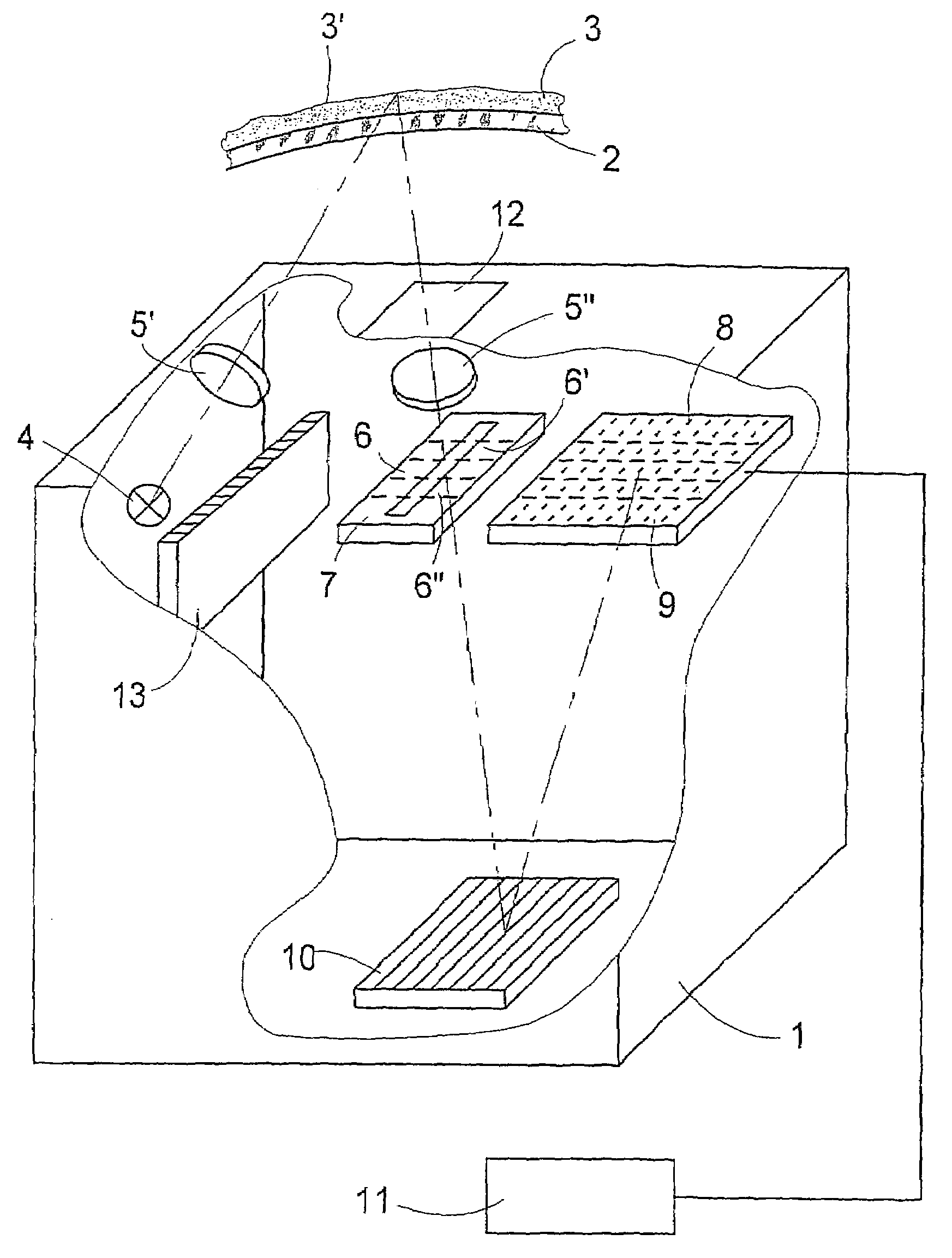
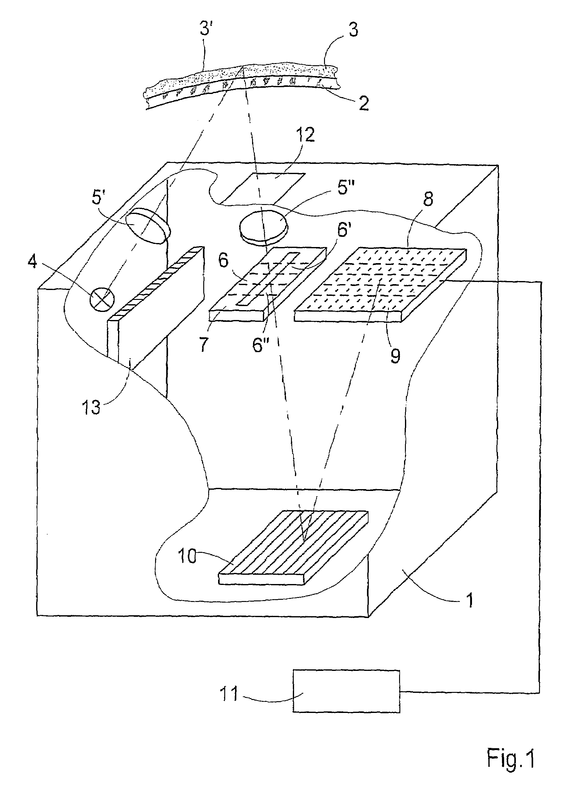
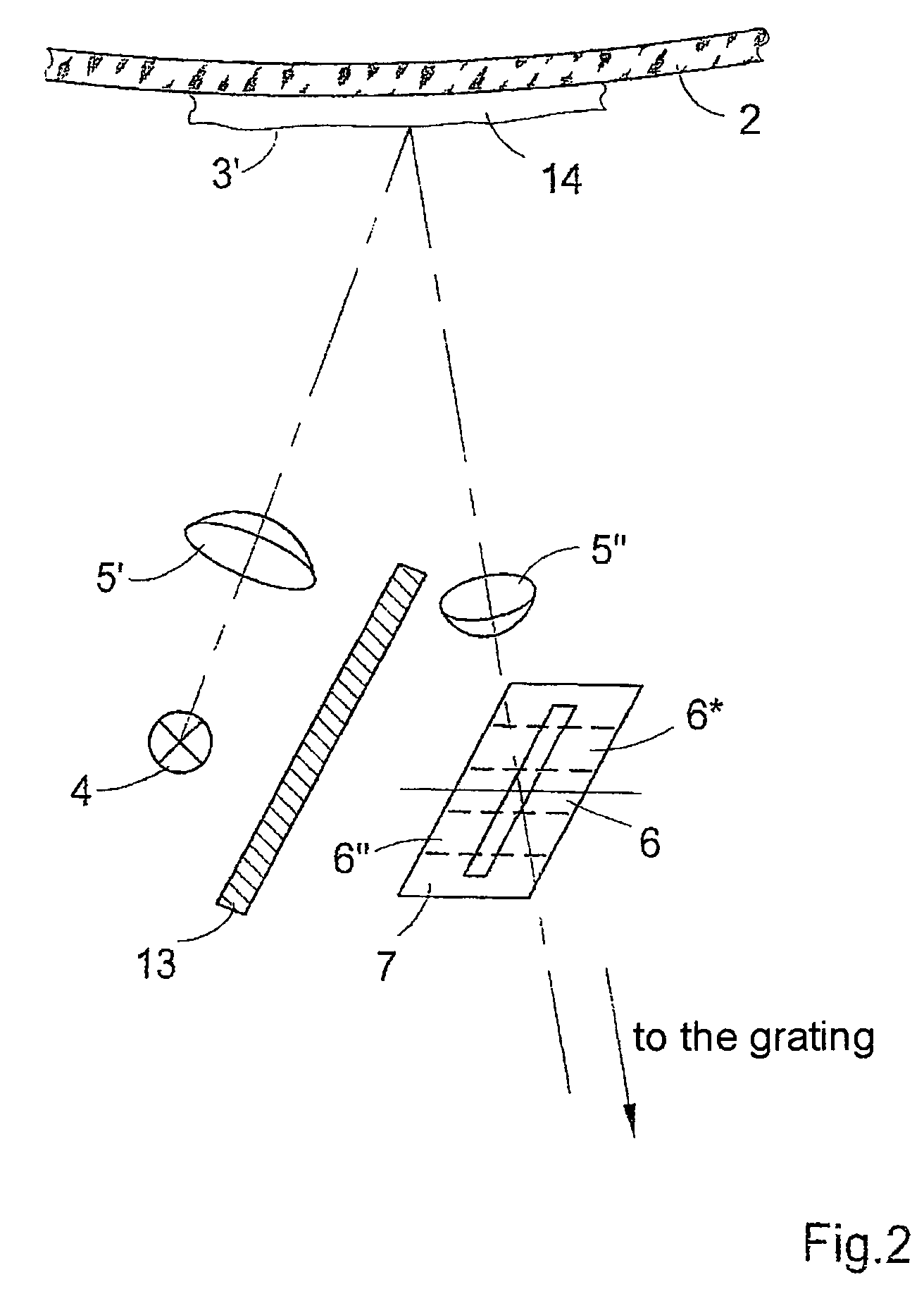
[0029]The arrangement shown in FIG. 1 for detecting coatings and determining their characteristics on surfaces, particularly coatings of water, ice and dirt on objects and in structural component parts of vehicles is basically a spectrometer. This arrangement comprises a housing 1. For the purpose of illuminating a coating 3 which is located on a transparent or opaque object 2, e.g., a windshield of a vehicle or a window pane, the housing 1 contains a light source 4, which emits radiation, and imaging optics which advantageously comprise a plurality of separate optical elements 5′ and 5″ for imaging the light source 4 along the coating 3 to be analyzed onto a larger or smaller limited portion 6 of the entrance slit 7.

[0030]When the distance between the coating 3 and the arrangement changes, which is usually the case in practice, it is necessary to image the light source 4 on the entrance slit 7 by means of a plurality of optical elements 5′ and 5″ in a telecentric beam path. Otherwi...


PUM


Abstract

The invention is directed to an arrangement for detecting coatings which are arranged on surfaces of structural component parts or objects and for determining the chemical characteristics and surface properties of these coatings. It comprises a light source for illuminating the coating to be analyzed on the surface of the structural component part and means for imaging the light source on an entrance slit over the surface of the coating to be analyzed. The entrance slit is imaged in a wavelength-dependent manner on a two-dimensional detector unit by a grating. An evaluating unit which is electrically connected to the detector unit serves to evaluate and process the signals supplied by the exposed detector elements of the detector unit.

Description

CROSS-REFERENCE TO RELATED APPLICATIONS[0001]This application claims priority of International Application No. PCT / EP03 / 04024, filed Apr. 17, 2003, and German Application No. 102 17 543.8, filed Apr. 17, 2002, the complete disclosures of which are hereby incorporated by reference.BACKGROUND OF THE INVENTION[0002]a) Field of the Invention[0003]The invention is directed to an arrangement and a method for detecting coatings lying on surfaces of structural component parts and for determining the characteristics thereof, in particular of coatings of water, ice and dirt on surfaces, preferably in structural components parts of vehicles. Above all, the chemical characteristics and surface properties of the coatings, particularly the roughness, are to be determined.[0004]b) Description of the Related Art[0005]In order to detect such coatings on surfaces of vehicle parts of this type and to determine their characteristics, these coatings are usually irradiated or penetrated by optical radiat...

Claims


Application Information

Patent Timeline
Patent Type & Authority Patents(United States)
IPC IPC(8): G01J3/36G01B11/30G01J3/02G01J3/04G01J3/28
CPCG01B11/306G01J3/02G01J3/0208G01J3/024G01J3/0262G01J3/2803G01J3/04G01B11/0616G01N21/8422G01N2021/8427G01N21/94G01N2021/945G01N2021/9586
Inventor FRITSCH, MANFREDCORRENS, NICOKERSTAN, FELIX
Owner CARL ZEISS MIKROLMAGING
Why Eureka
Try Eureka