
Method and apparatus for client-side flow control in a transport protocol

a client-side and transport protocol technology, applied in the field of network transport protocols, can solve the problems of reducing the computational load of the server device to determine the flow control of tcp, limiting server performance, and affecting the performance of the server, so as to reduce the computational load of the server devi

Inactive Publication Date: 2009-03-10
CISCO TECH INC
View PDF33 Cites 64 Cited by
  • Summary
  • Abstract
  • Description
  • Claims
  • Application Information

AI Technical Summary

Benefits of technology

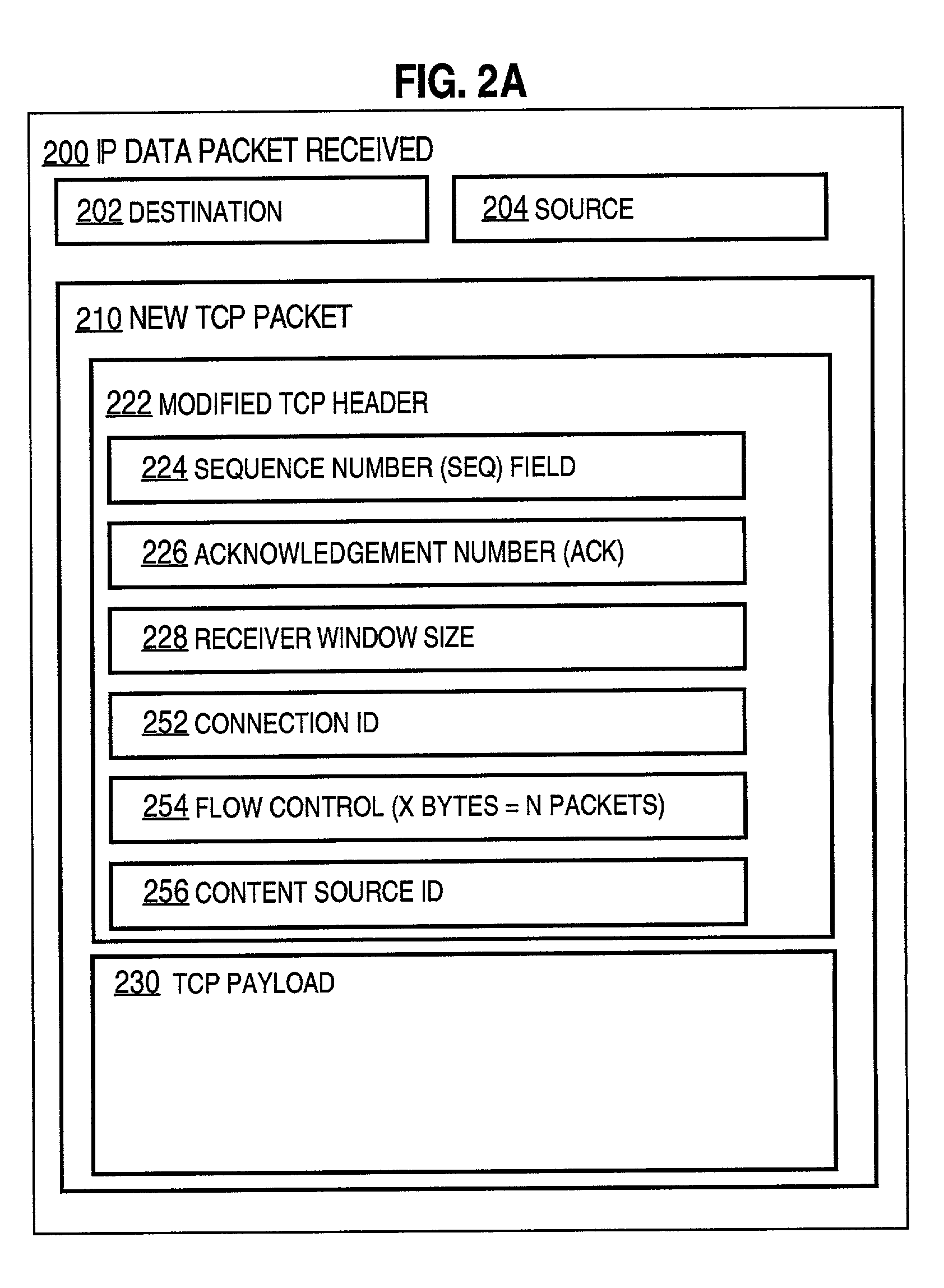
[0015]The foregoing needs, and other needs and objects that will become apparent from the following description, are achieved in the present invention, which comprises, in one aspect, a method for providing reliable transport of data across a network between a server on a server device and a client on a client device requesting multiple packets of content from the server. A process on the client device determines a number of packets to be sent by the server device without an acknowledgement message from the client device based on considerations of network problems. A data packet is sent to the server device. The data packet includes a first field holding data indicating the number of packets to be sent by the server device without an acknowledgement message from the client device.
[0020]The techniques of the present invention allow a transport layer process on a client device to download large amounts of content from a stateless transport layer process on a server device, substantially reducing the computational resources consumed by the server device in serving thousands of clients.

Problems solved by technology

This includes the burden of detecting network congestion and deciding when to retransmit.
A disadvantage of the current implementation of TCP becomes apparent when a single server device attempts to transmit data to thousands of clients.
In such a case, the computational load on the server device to determine flow control for TCP becomes a limiting factor in server performance.
For example, the amount of power consumed by the particular equipment suite used by the server increases substantially with the number of clients; and ultimately the number of clients that the particular equipment suite can serve may be limited.
As more clients request services, expensive new equipment may have to be purchased and installed to meet the client demands.
However, this approach does not handle requests that prompt a server to provide multiple data packets in response.
The stateless TCP transmitter is not able to process acknowledgements or determine when a particular data packet should be retransmitted, because the stateless TCP process does not record the time and contents of data packets already sent.
A disadvantage of this approach is the excessive network traffic generated by acknowledging each data packet and the resulting slow transfer for connections with large round-trip time (RTT) characteristics.

Method used


Image

  • Method and apparatus for client-side flow control in a transport protocol
  • Method and apparatus for client-side flow control in a transport protocol
  • Method and apparatus for client-side flow control in a transport protocol

Examples


embodiment 300

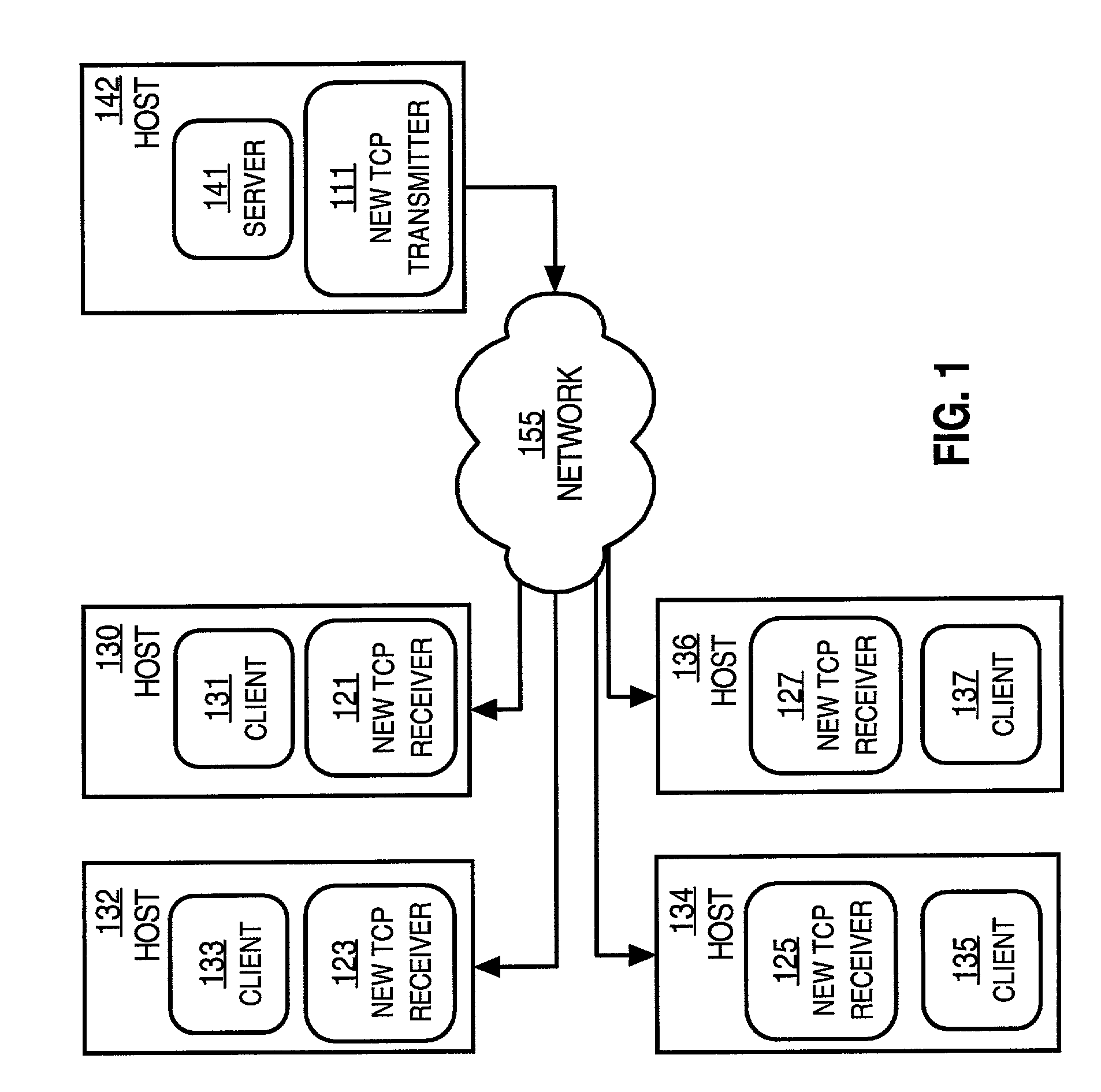
[0088]FIG. 3 is a flowchart that illustrates a high level overview of one embodiment 300 of a method executed on a client device for providing reliable transport with a stateless transport layer process on a server device. For example, the steps of embodiment 300 are performed by the new TCP receiver process 121 on client device 130 for client 131 to obtain multiple data packets of content from a stateless new TCP transmitter process 111 on host 142 for server 141. Although steps are illustrated in FIG. 3 and following flowcharts in a particular order, in other embodiments the steps can be performed in a different order, or overlapping in time.

[0089]For purposes of illustration, the description herein assumes that Table 1 lists the values selected and data packets that are sent, for an example with no lost data packets. Also for purposes of illustration, the description herein assumes that Table 2 lists the values selected and data packets that are sent for an example with one lost ...

embodiment 400

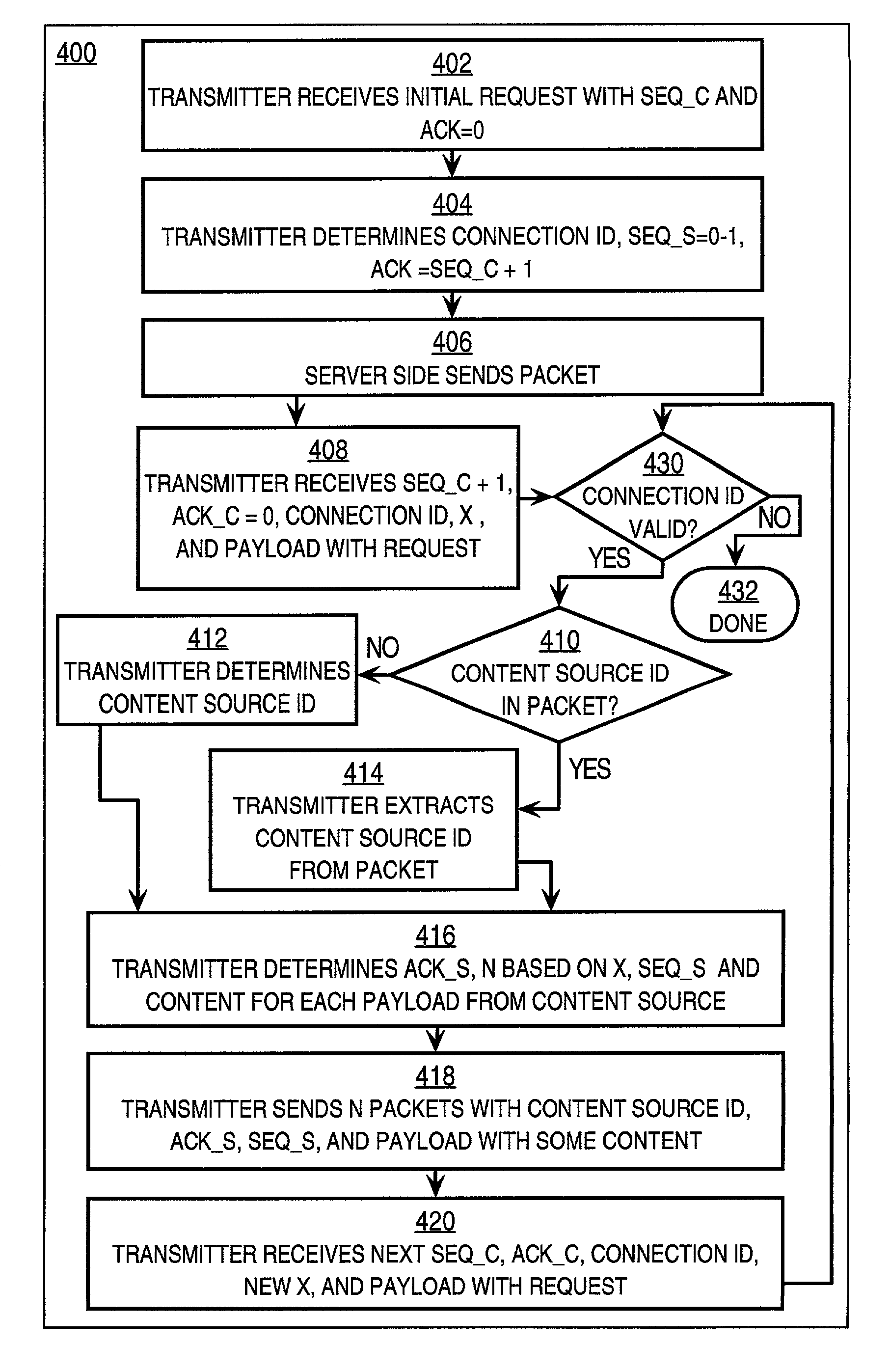
[0143]FIG. 4 is a flowchart that illustrates a high level overview of embodiment 400 of a method executed by a stateless transport layer process on a server device for providing reliable transport with a client device. The operation of method 400 is illustrated with the example of Table 1. The performance of the method 400 does not depend on network considerations, such as lost data packets or detecting network congestion.

[0144]In step 402, the stateless new TCP transmitter 111 on the server side receives the first data packet 261 with an arbitrary SEQ_C1 value in the SEQ field 224 and an arbitrary value ACK_C1 in the ACK field 226. The value ACK_C1 is ignored. For example, as shown in Table 1, the first data packet includes SEQ_C1=1111 and ACK_C1=0. This data packet is recognized as a first step in the three-way handshake to establish a connection by the SYN bit of the conventional TCP header.

[0145]In step 404, the transmitter 111 sets the value ACK_S2 for the second data packet by...


PUM


Abstract

Techniques for providing reliable transport of data across a network between a server on a server device and a client on a client device include a process on the client device which determines a number of packets to be sent by the server device without an acknowledgement message from the client device. The number of packets is based on considerations of network problems. A data packet sent to a server device includes a first field holding data indicating the number of packets to be sent by the server device without an acknowledgement message from the client device. Accordingly, a transport layer process on a client device to download large amounts of content from a stateless transport layer process on a server device, substantially reducing the computational resources consumed by the server device in serving thousands of clients.

Description

CROSS REFERENCE TO RELATED APPLICATION[0001]This application claims benefit as a Continuation-in-part of application Ser. No. 09 / 901,523, filed Jul. 9, 2001, by J.-P. Champagne and J. Aviani, the entire contents of which is hereby incorporated by reference for all purposes as if fully set forth herein, under 35U.S.C. §120.FIELD OF THE INVENTION[0002]The present invention generally relates to network transport protocols providing reliable transfer of all data packets in a communication from a server process to a client process. The invention relates more specifically to a client-side flow control in a transport protocol based on network problems.BACKGROUND OF THE INVENTION[0003]According to the Open Systems Interconnect (OSI) network model, functions involved in transferring data among devices in a network are distributed among different logical layers. The lowest layer represents physical network device hardware. Above that is a data link layer that places bits onto physical links a...

Claims


Application Information

Patent Timeline
IPC IPC(8): G06F15/16G01R31/08
CPCH04L47/10H04L47/193H04L47/26H04L47/34H04L69/26H04L69/16H04L69/163H04L69/326H04L47/267
Inventor CHAMPAGNE, JEAN-PHILIPPE
Owner CISCO TECH INC
Learn More