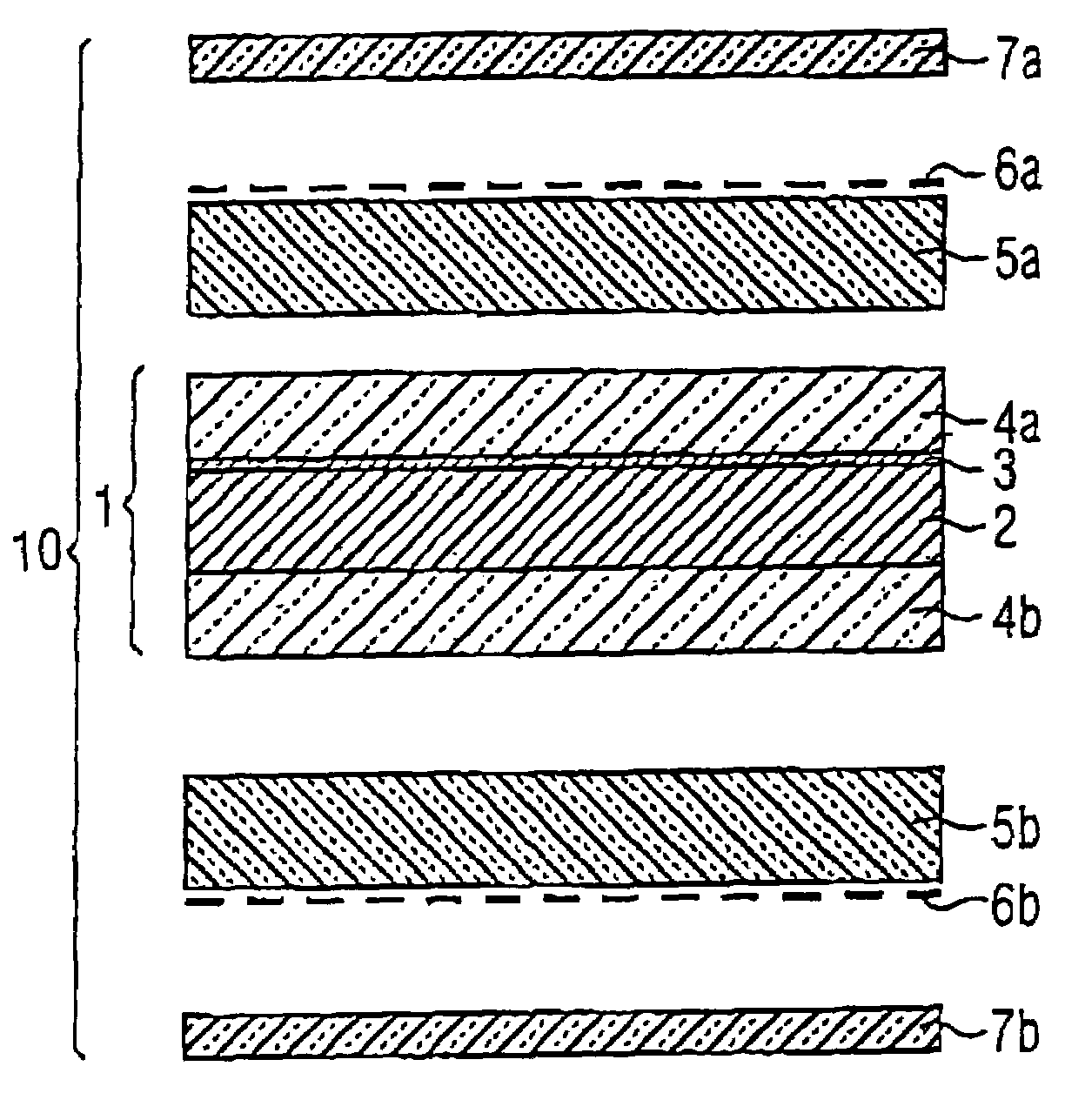
[0012]Accordingly, the card laminate comprises an interior layer provided with a
metal layer partially or all over at least on one side, and a first plastic layer on each side of the interior layer. The first plastic layer overlying the metallized side is transparent so that the metal layer is recognizable from outside as an optically brilliant background for a printed image to be explained more closely hereinafter. The interior, metallized layer and the two adjacent plastic layers are provided as a foil laminate, which can preferably remain unprinted but which can also be printed. This has the
advantage that the scratch-sensitive
metal coating is mechanically protected against external influences by the two exterior first plastic layers. The foil laminate can therefore be safely produced, stored and processed further. The reject rate of the expensive metallized foil is accordingly low.
[0014]This offers various advantages. On the one hand, it is thus possible to produce the printed image on standard films, for example made of PVC, by any printing method, in particular without the necessity of previously applying a primer. On the other hand, the central foil laminate and the film provided with the printed image can be produced in completely different places of production and only laminated into the inventive card laminate at a considerably later stage of the method. If the central foil laminate remains unprinted, no rejects due to misprints can thus occur. Rejects then only result in connection with the inexpensive PVC films.
[0015]Finally, the distance of the printed image from the metal layer makes it possible—due to the first plastic layer therebetween—to obtain three-dimensional effects or shadow effects against a background with metallic luster. If the printed image is located on the outer side of the second plastic layer, the distance from the metal layer is particularly great and the thus obtained 3D effect maximal.
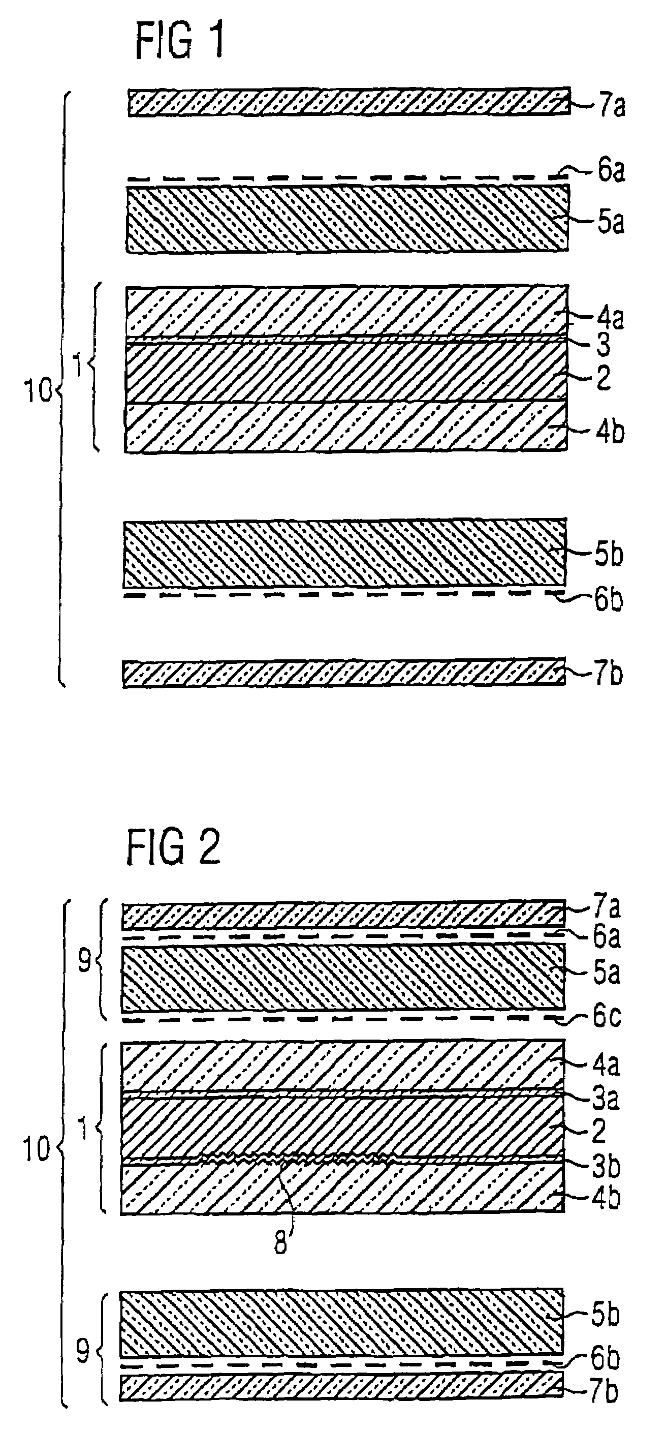
[0016]According to a preferred embodiment, the transparent
plastic film forming the second plastic layer is printed on both sides, so that two printed images are disposed in different planes spaced in front of the metal layer. This permits a special 3D effect to be obtained. Alternatively, the second printed image can also be printed on the outer side of the first transparent plastic layer of the central foil laminate, but this is less preferable because of the danger of rejects due to misprints on the expensive foil laminate. This rejects problem can be avoided, however, if the plastic layer of the central foil laminate is printed before it is laminated with the metallized foil to form the foil laminate.
[0017]If the second plastic layer is printed on the outer side, it is advantageous for protecting the printed image to provide the card laminate with a transparent cover layer over the printed image. Said transparent cover layer is provided according to one embodiment as a separate film and laminated together with the central foil laminate and the second plastic layers present as plastic films into the inventive card laminate. According to an alternative embodiment, the transparent cover layer can be applied to the second plastic layer in advance, for example as transparent
lacquer or again as a film laminated on. In this case the second plastic layer is thus provided together with the cover layer as a laminate and laminated with the central foil laminate into the final card laminate.
[0021]According to a development of the invention, at least one metallized area of the interior layer has a diffractively effective relief structure, which can be produced for example by an
embossing method preferably before or optionally only after metallization. The relief structure can also extend all over the interior layer. This makes it possible to realize holographic effects and other diffractive effects—for example a
rainbow effect—in the background of the printed image. Diffractively effective relief structures to be used are
refraction patterns, holograms, but also lattice structures (e.g. Kinegrams®, Pixelgrams) or the like. The interior plastic layer can again be equipped with the metallized relief structure on one side or on both sides.

