Method for producing a magnetic tunnel junction and magnetic tunnel junction thus obtained

a technology of magnetic tunnel junction and magnetic tunnel junction, which is applied in the direction of magneto-resistive sensors, instruments, vacuum evaporation coatings, etc., can solve the reliability problems of magneto-resistive sensors, the inability to sufficiently reduce the ra product, and the difficulty in reaching in a reliable and reproducible way

Inactive Publication Date: 2011-11-03
COMMISSARIAT A LENERGIE ATOMIQUE ET AUX ENERGIES ALTERNATIVES +1
View PDF11 Cites 43 Cited by
  • Summary
  • Abstract
  • Description
  • Claims
  • Application Information

AI Technical Summary

Benefits of technology

[0047]Here too, the perovskite is to advantage polycristalline.
[0048]According to the invention, the perovskite is selected to advantage from the group that includes strontium titanate (SrTiO3), BaTiO3, and more generally compounds of formula [Ba1-xSrx]TiO3 with x between 0 and 1, SBT (SrBi2Ta2O9) and SBN (SrBi2Nb2O9).

Problems solved by technology

However, this approach raises reliability problems with the magneto-resistive sensor.
But the usual materials AlOx, MgO do not allow the RA product to be lowered sufficiently (tunnel barrier height too high as explained below).
These values are difficult to reach in a reliable and reproducible way and without significant loss of tunnel magneto-resistance amplitude with materials like AlOx or MgO.
If in terms of the physical principle, the operation of these magnetic tunnel junctions has been demonstrated, there is on the other hand a difficulty with industrialisation to be overcome.
But it is known to those skilled in the art that if the thickness of the tunnel barrier is reduced below 0.8 nanometres, the uniformity if not the continuity of the barrier is no longer guaranteed, which causes a rapid drop in the TMR.in the memory field, it is the write mode that requires the RA product to be reduced to extremely low values.
Prior art magnetic tunnel junctions in fact have a great many limitations.
First of all, for magnetic tunnel junctions with MgO barrier of low RA product, i.e. close to 0.5 Ω·m2, the value of the TMR is relatively small, and typically close to 50% because of the inhomogeneity effects of the barrier thickness, which reduces the read (voltage) signal and creates hot points in the tunnel barrier (zone of highest current density), increasing the risks of electrical breakdown of the tunnel junction.
Furthermore, the height of such tunnel barriers is significant, and typically close to 7.5 eV, so that very low RA products cannot in this way be attained, while guaranteeing good reliability (risk of breakdown given the very small degree of barrier thickness required).
What is more, complex oxidation methods are encountered in producing the tunnel barrier since more often than not the starting point is a pure magnesium target.
However, given the crystallization temperature of the strontium titanate, it has not hitherto been possible to develop such magnetic tunnel junctions.
Indeed; this crystallization temperature remains very high, above 500° C., and therefore not compatible with the materials employed for the magnetic electrodes located on either side of the tunnel barrier.
Indeed, a crystalline SrTiO3 barrier is traditionally made by physical vapour deposition (PVD) such as cathode sputtering for example or by laser ablation and generally requires elaboration (deposition or annealing) temperatures typically of between 550 and 800° C., which is consequently incompatible with the magnetic films constituting the stack.

Method used


Image

  • Method for producing a magnetic tunnel junction and magnetic tunnel junction thus obtained
  • Method for producing a magnetic tunnel junction and magnetic tunnel junction thus obtained

Examples


Embodiment Construction

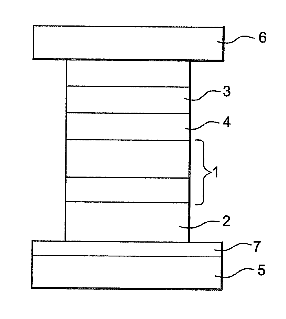
[0054]FIG. 1 therefore shows a magnetic stack obtained in accordance with the invention, and more specifically intended to constitute a memory point or cell of a magnetic random access memory (MRAM).

[0055]Conventionally, this comprises a locked film 1, in the case in point comprising a film made of a CoFeB alloy 2 nanometres thick, and a film of CoFe 2 nanometres thick. This locked film is coupled magnetically with a film 2 with antiferromagnetic properties, and in the case in point made of an IrMn alloy 6-7 nanometres thick.

[0056]This locked film is separated from a free film 3, also made of CoFeB alloy, and in the case in point ˜3 nanometres thick, by the tunnel barrier 4 made of perovskite, and for example of strontium titanate SrTiO3, with a thickness of less than 1.5 nanometres. Alternatively, the material may be barium titanate or Strontium and Barium titanate (SBT (SrBi2Ta2O9)), SBN (SrBi2Nb2O9)), these different materials having a simple or double Perovskite structure.

[0057]...


PUM

PropertyMeasurementUnit
temperatureaaaaaaaaaa
impedanceaaaaaaaaaa
impedanceaaaaaaaaaa

Abstract

According to this method for producing a magnetic tunnel junction, a film of a dielectric material capable of acting as a tunnel barrier is deposited between two nanocrystalline or amorphous magnetic films. The dielectric material constituting the tunnel barrier consists of an at least partially crystalline perovskite, and said material is deposited by ion beam sputtering in a vacuum chamber.

Description

FIELD OF THE INVENTION[0001]This invention relates to the field of magnetic elements with magnetic tunnel junction with so-called “tunnel magneto-resistance” response.[0002]It can be used particularly in radio-frequency oscillators and in the read heads of hard disks. It also relates to non-volatile magnetic random access memories, used in a known way for storing, reading and writing data in electronic systems.PRIOR ART[0003]In the field of ultra-high density magnetic recording, the magnetic field sensors used since 1992 in the read heads of computer hard disks are based on magneto-resistive materials which allow variations in magnetic field at the surface of the magnetic media to be converted into voltage variation at the terminals of the magneto-resistive sensor. So that there is good impedance matching with the pre-amplifier which pre-amplifies the sensor signal prior to the signal processing chain, research is being conducted into producing sensors which have impedance of the or...

Claims


Application Information

Patent Timeline
Patent Type & Authority Applications(United States)
IPC IPC(8): H01L29/82H01L21/20
CPCB82Y25/00B82Y40/00H01F41/307C23C14/46H01F10/3254C23C14/088G11C11/16H10N50/10H10N50/01H10N50/85
Inventor VIALA, BERNARDCYRILLE, MARIE-CLAIREDIENY, BERNARDGARELLO, KEVINREDON, OLIVIER
Owner COMMISSARIAT A LENERGIE ATOMIQUE ET AUX ENERGIES ALTERNATIVES
Why Eureka
Try Eureka