Additive for lithium ion rechageable battery cells

a lithium ion rechargeable battery and additif technology, applied in secondary cells, non-aqueous electrolyte cells, cell components, etc., can solve the problems of increasing the likelihood of structural breakdown of the active material of the anode during expansion and contraction, the volume change of the silicon anode material in the li-ion cell, and the short cycle life of the electrode, so as to reduce the resistance of the anode, increase the conductivity, and increase the electrical conductivity of the anod

Active Publication Date: 2015-02-03
SK ON CO LTD
View PDF281 Cites 43 Cited by
  • Summary
  • Abstract
  • Description
  • Claims
  • Application Information

AI Technical Summary

Benefits of technology

[0057]In particular, we believe that the balance between achieving (a) a good SEI layer that is neither too thick nor too thin, (b) good anode performance and (c) a good anode lifetime is best achieved by using specific structured silicon material or particles in the presence of VC and optionally also one or two fluorinated ethylene carbonates, namely FEC and / or difluoroethylene carbonate (DFEC), in specific amounts.
[0148]In addition to the structured silicon-containing material as described above, e.g. fibres; felts; scaffolds; pillar bundles; tubes; porous particles; or pillared particles, the anode can include other active materials, i.e. materials that can be lithiated and delithiated during the cycling of the battery cell for example graphite or tin. However, at least 5 wt %, suitably at least 10 wt %, more suitably at least 20 wt %, optionally at least 50 wt % and preferably at least 70 wt % of the active material in the anode is the above structured silicon. The anode can also include other known additives, e.g. forms of carbon black, acetylene black or carbon fibres which are known to be added to lithium cells to increase the conductivity of the anodes. Each electroactive material-containing particle can be composed wholly of one type of electroactive material or can include other active or non-active material, e.g. carbon or tin; where the other material is non-active, it may enhance the electrical conductivity of the anode. For example, the electroactive material may be carbon-coated. In particular, each silicon-containing particle can be composed wholly of silicon or can include other active or non-active material, e.g. carbon or tin; where the other material is non-active, it may enhance the electrical conductivity of the anode. For example, the silicon may be carbon-coated.

Problems solved by technology

Unfortunately silicon anode material in Li-ion cells undergoes a huge volume change between the charged and the discharged states associated with the insertion and removal of lithium ions into the silicon material during the charging and discharging stages of the cells.
As a consequence of such expansion and contraction, which on each cycle causes mechanical degradation of the silicon material and electrical isolation of sections, the electrodes can have a short cycle life.
It is believed that the likelihood of structural breakdown of the anode active material during expansion and contraction can increase if crystalline and amorphous Li—Si alloy phases are allowed to co-exist during a charge-discharge cycle.
A drawback of the SEI formation is that it consumes some of the lithium and electrolyte components, and ties them up in the system, preventing them from contributing to the charge capacity of the cell.
Excessive SEI formation will lead to an increased ionic resistance and degrade the cell performance.
After the first cycle, the repeated expansion and contraction of the silicon during cycling can cause cracks in the SEI, exposing fresh silicon surfaces, leading to production of more SEI layer, consuming further liquid electrolyte and lithium.
This reduces the cell charge / discharge efficiency, can cause the cell to dry out, and further reduces available cycle life.
Further, the structure of the anode material greatly affects the formation of the SEI layer.
Such structures have a more convoluted surface morphology than simple (i.e. unstructured) silicon particles or films and have lots of sharp corners and changes in surface directions, which makes it more difficult to form a thin, flexible (elastic), non-porous SEI coating over the whole exposed silicon surface.
However, the teaching of this citation is limited to the type of anode material used (a thin film of amorpohous silicon or fine crystalline silicon with nm-sized grains).
Again this teaching is limited to the special powdered or thin film alloy anode material used.
The presence of hydrogen fluoride would normally be considered detrimental to lithium ion battery performance, because it reacts with lithium carbonate to produce lithium fluoride, water and carbon dioxide.
However this also causes disadvantages: in the case of thin films (see for example the Libao Chen et al. article discussed above), it reduces the available anode capacity per unit volume; in the case of sub-micron particles it increases the silicon surface area to volume ratio, which increases the proportion of SEI formed during operation and the consumption of lithium and the electrolyte.
The long range connectivity within the active material is also poorer with spherical nano-particles.
Further there are no examples of base solvents other than unsubstituted cyclic carbonates and linear carbonates.

Method used


Image

  • Additive for lithium ion rechageable battery cells
  • Additive for lithium ion rechageable battery cells
  • Additive for lithium ion rechageable battery cells

Examples


example 1

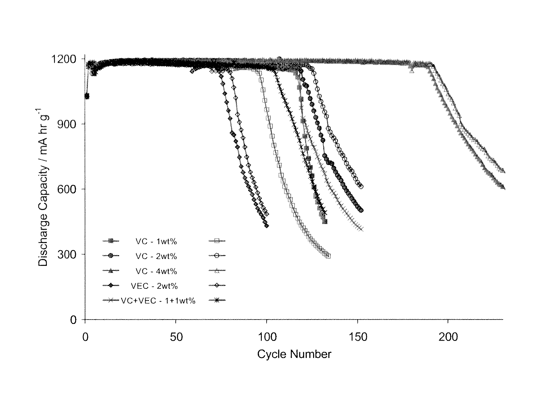
[0194]Electrolytes containing various amounts of vinylene carbonate (VC) and vinylene ethyl carbonate (VEC) were made up and used in several soft pack pair cells with the parameters outlined in Table 1. The active anode material in each cell was silicon fibres of diameter 100-200 nm and length 30-80 μm. This material was made by etching a silicon wafer and severing the pillars from the substrate, e.g. ultrasonically, to form the fibres (as described above and in WO 2007 / 083155).

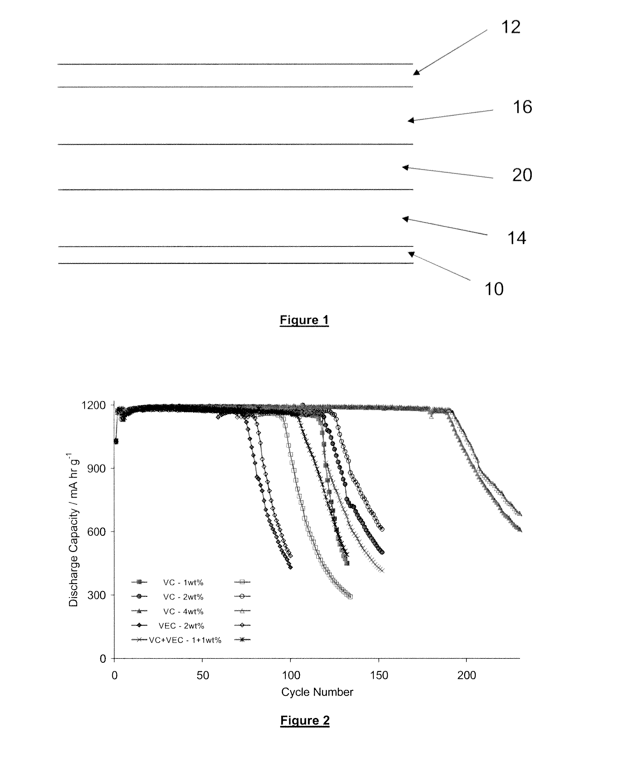
[0195]In a series of cycles, each cell was charged up to a capacity of 1200 mA·hr·g−1 and then discharged over time. The discharge capacity was measured and the results are shown in FIG. 2. The ability to maintain a discharge capacity of 1200 mA·hr·g−1 over a number of charging / discharging cycles is indicative of the expected life of the rechargeable battery.

[0196]In the graphs of FIG. 2, two cells containing each of the following additives were tested:[0197]2% VEC[0198]1% VC[0199]1% VC plus 1% VEC[0200]2% VC...

example 2

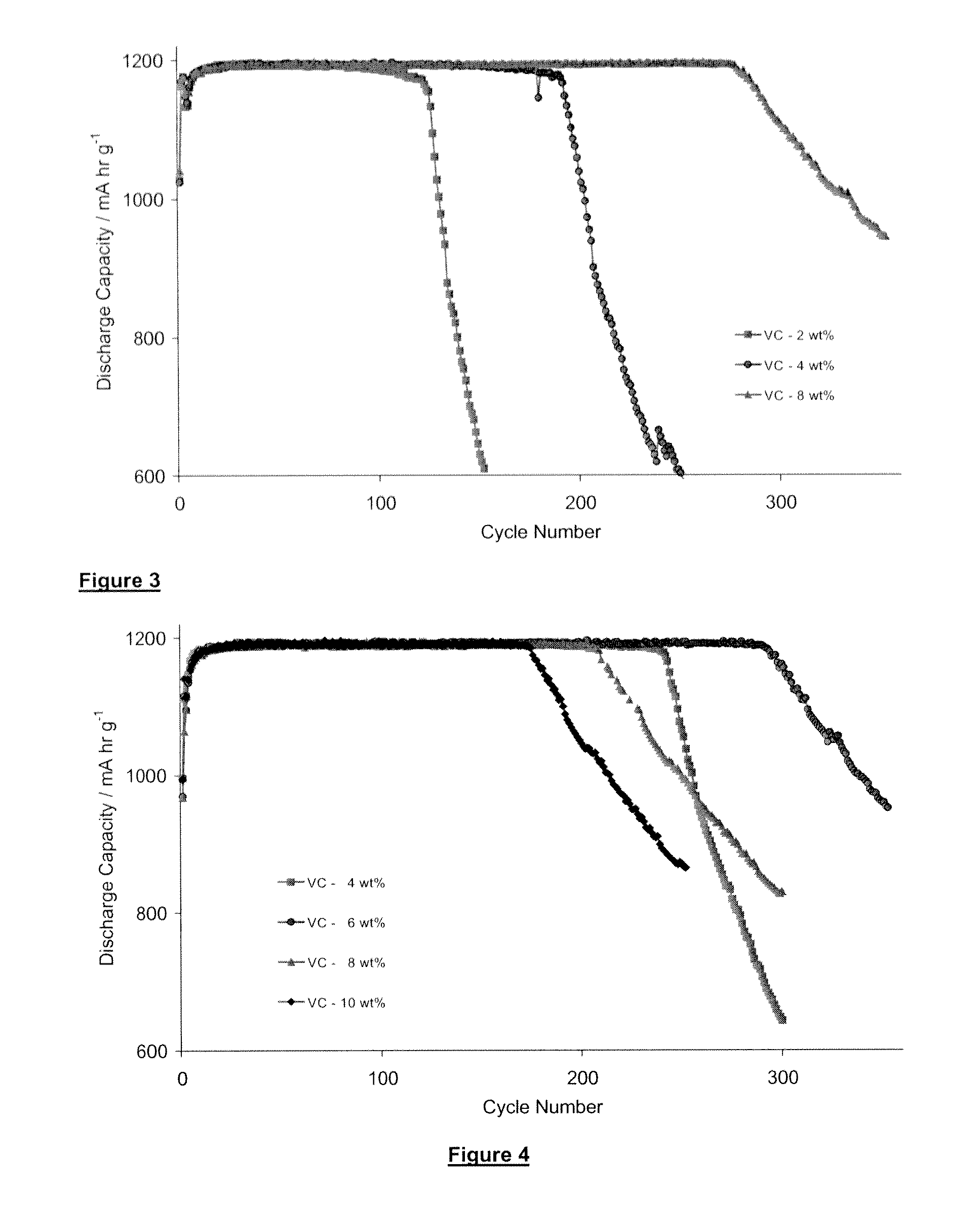
[0203]A test similar to that described above in connection with Example 1 was conducted but with a wider range of VC additives (2% VC, 4% VC and 8% VC). Again, the soft pack test cells used fibre silicon from wafer as described above and were charged to 1200 mAhr / g. The results are shown in FIG. 3, where it is clear that the addition of 8% VC produces a marked improvement in cell life as compared to adding 2 or 4% VC.

[0204]It should be noted that the number of cycles that a given cell achieves before a decline in its capacity in respect of a given electrolyte composition is dependent also on other factors of a given cell, including the electrode thickness (weight) and the ratio of cathode active material to silicon anode material. It also depends on the particular conditions prevailing the time, including temperature, charge / discharge rate and the depth of discharge. In any one graph described herein, the cells tested are designed to minimise these extraneous factors. However, the f...

example 3

[0205]A further batch of soft pack pair cells, with parameters as listed in Table 1 and 2 were used to test a broader and higher range of VC additives, ranging from 4% to 10%. The cells were similar to those in examples 1 and 2, with the same anode material (fibres) charged to 1200 mAhr / g except that the anode coat weight was higher. The results are shown in FIG. 4, where the plots indicate the following percentages of VC additive:[0206]4% VC[0207]6% VC[0208]8% VC[0209]10% VC

[0210]As can be seen from FIG. 4 the advantage of increased battery life falls off when 10% VC is added but is a maximum at about 6% VC.


PUM

PropertyMeasurementUnit
lengthaaaaaaaaaa
diameteraaaaaaaaaa
lengthaaaaaaaaaa

Abstract

The present invention claims the addition of vinylene carbonate (VC) and optionally also fluoroethylene carbonate to the electrolyte of lithium ion cells having a structural silicon composite anode, i.e. an anode containing fibers or particles of silicon. The additive significantly improves the cycling performance of the cells. A VC content in the range 3.5-8 wt % based on the weight of the electrolyte has been found to be optimum.

Description

TECHNICAL FIELD[0001]The invention relates to lithium ion rechargeable battery cells, to electrolyte solutions used in such cells and especially to electrolyte solutions containing certain amounts of additives.BACKGROUND ART[0002]Lithium-ion rechargeable battery cells currently use a carbon / graphite-based anode. The basic composition of a conventional lithium-ion rechargeable battery cell including a graphite-based anode electrode is shown in FIG. 1. A battery may include a single cell but may also include more than one cell.[0003]The battery cell generally comprises a copper current collector 10 for the anode and an aluminium current collector 12 for the cathode, which are externally connectable to a load or to a recharging source as appropriate. It should be noted that the terms “anode” and “cathode” are used in the present specification as those terms are understood in the context of batteries placed across a load, i.e. the term “anode” denotes the negative pole and the term “cat...

Claims


Application Information

Patent Timeline
Patent Type & Authority Patents(United States)
IPC IPC(8): H01M4/13H01M4/62H01M6/16H01M4/134H01M10/0525H01M10/056H01M10/0566H01M10/0567H01M10/0568H01M10/0569H01M10/44H02J7/00
CPCH01M10/056H01M4/134H01M10/0525H01M10/0566H01M10/0567H01M10/0568H01M10/0569H02J7/0052H01M10/44Y02E60/122H01M4/38H01M4/386H01M4/387H01M2300/0034Y02E60/10H01M4/36H01M10/052H01M2300/0025H02J7/00
Inventor COOWAR, FAZLILABDELSALAM, MAMDOUH ELSAYEDLAIN, MICHAEL JONATHAN
Owner SK ON CO LTD
Why Eureka
Try Eureka