Projection optical system

a technology of projection optical system and optical system, which is applied in the field of projection optical system, can solve the problems of increasing the number of components, increasing the cost of the entire apparatus, further cost increase and upsizing, and achieves the effect of favorable optical performance and high accuracy

Inactive Publication Date: 2009-03-17
KONICA MINOLTA OPTO
View PDF5 Cites 10 Cited by
  • Summary
  • Abstract
  • Description
  • Claims
  • Application Information

AI Technical Summary

Benefits of technology

[0011]In view of the problem described above, the present invention has been made, and it is an object of the invention to provide a low-cost, compact projection optical system capable of performing pixel shift with high accuracy while maintaining a favorable optical performance.

Problems solved by technology

However, with the projector constructions proposed in Patent publications 1 to 3, image projection is performed with an optical power possessed by a refractive optical system; therefore, an increase in the number of components and an increase in the back focus as a result of adding a mirror or a flat glass leads to upsizing of the entire apparatus and a cost increase.
Especially in a case where a mirror or a flat glass to be slightly decentered is large in size, this results in upsizing of mechanisms such as a holding mechanism, a decentering mechanism, and the like, and thus requires complicated mechanisms for achieving slight decentering with even more accuracy, which contributes a further cost increase and upsizing.
Further, the projector proposed in Patent document 2 suffers from chromatic aberration occurring with the flat glass to be slightly decentered.

Method used


Image

  • Projection optical system
  • Projection optical system
  • Projection optical system

Examples


examples

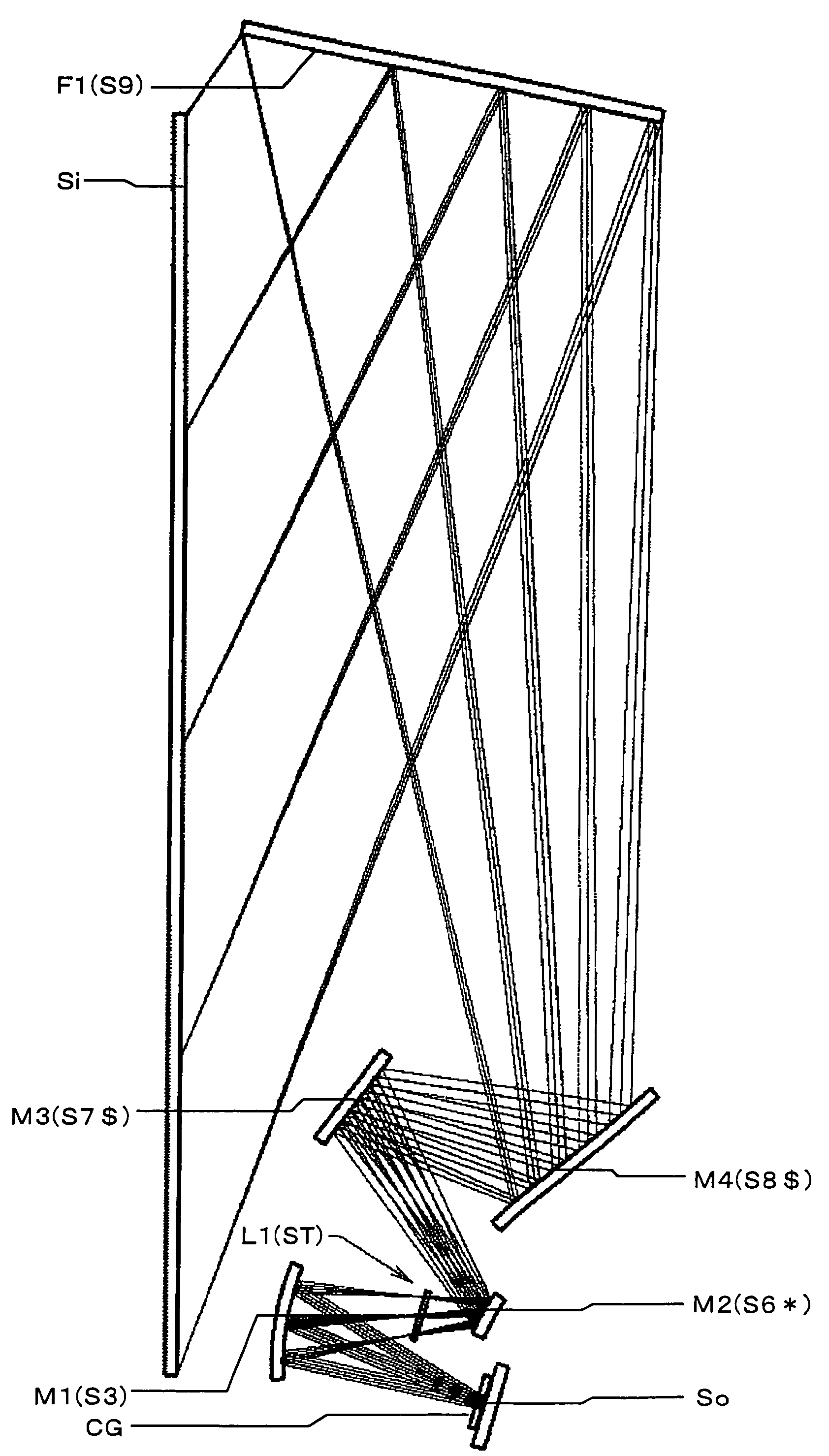
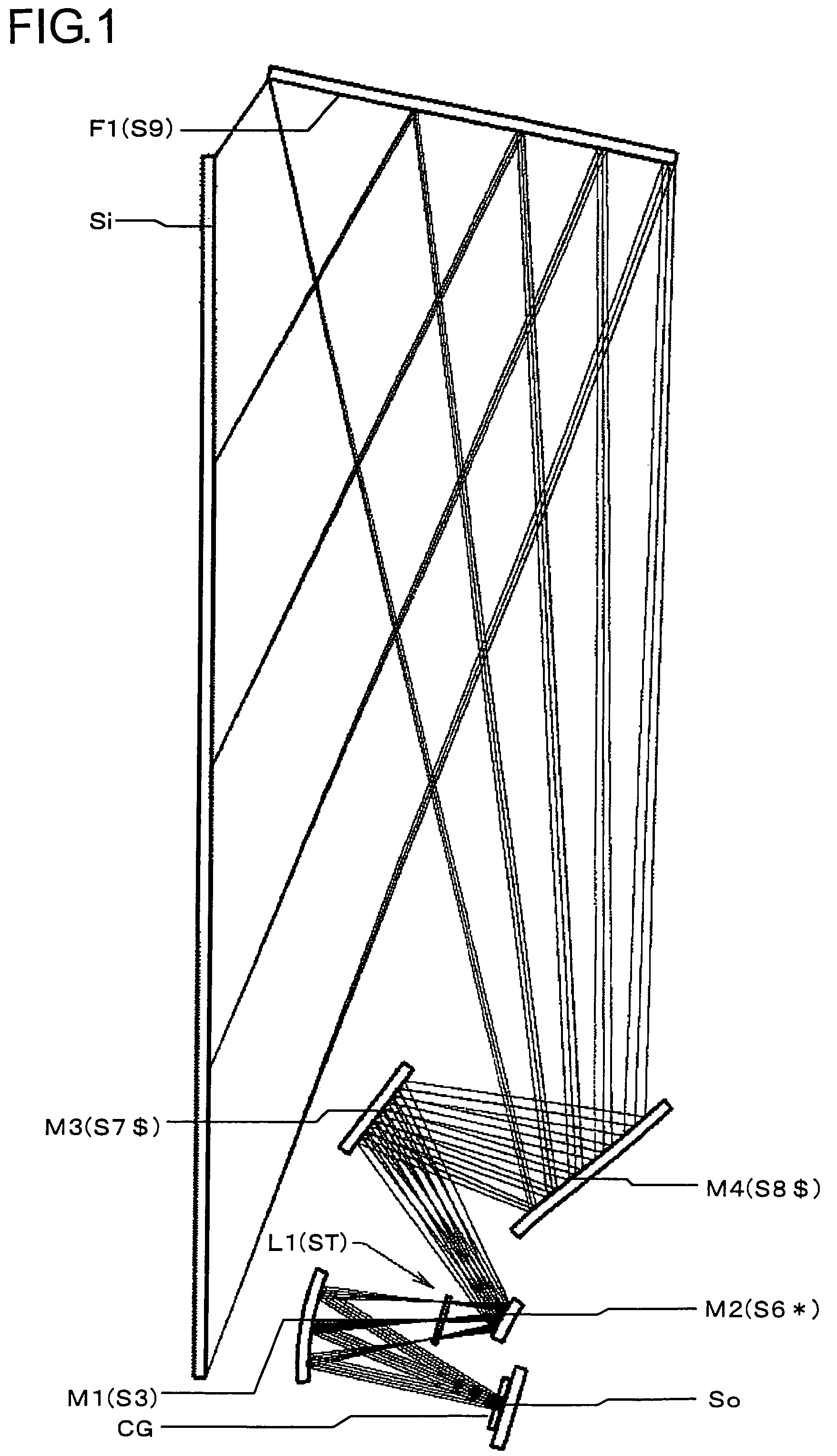
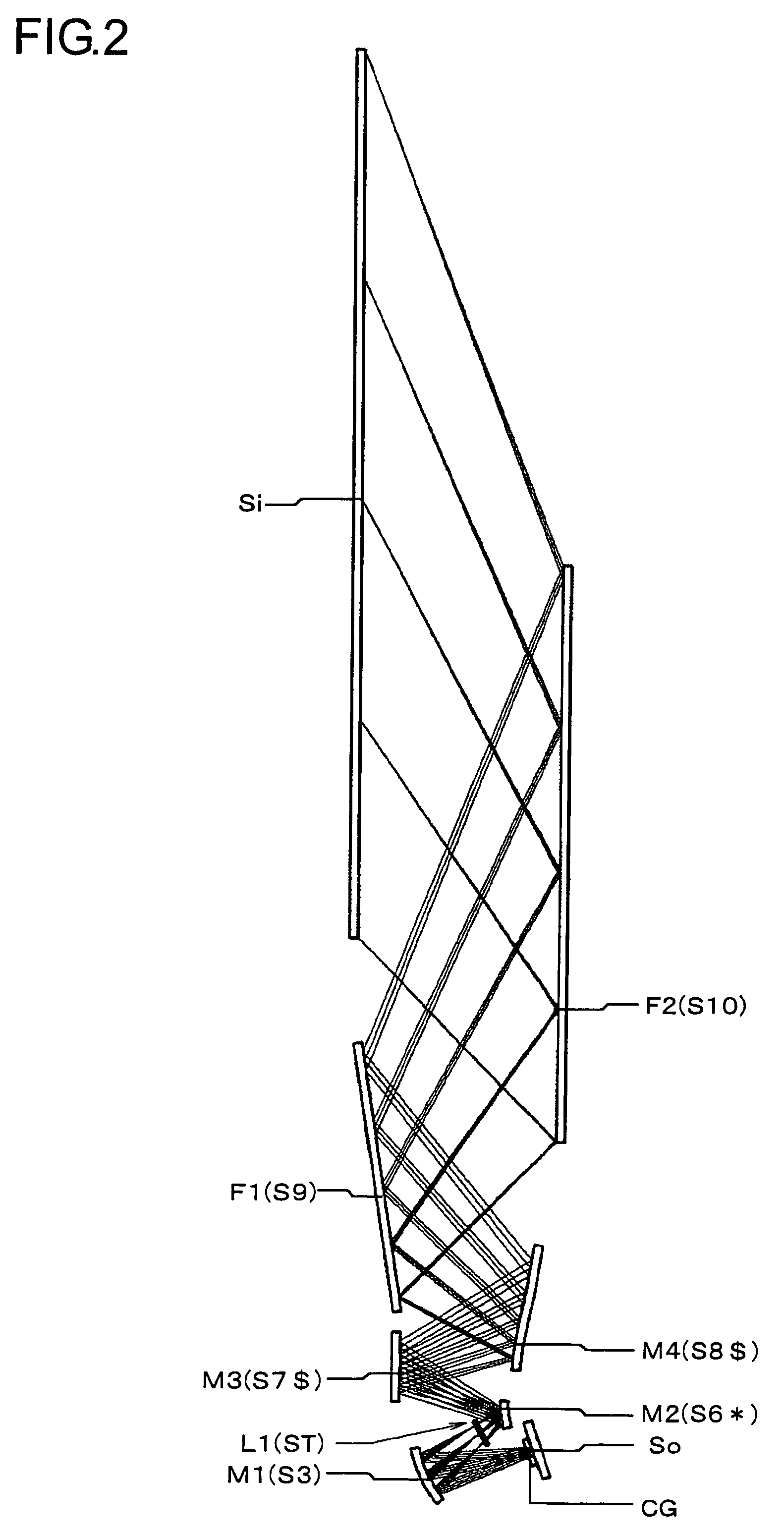
[0060]Hereinafter, practical examples of the projection optical system embodying the present invention will be presented with reference to their construction data and the like. Examples 1 to 5 presented below are numerical examples of projection optical systems corresponding to the first to fifth embodiments, respectively, described previously. Thus, the optical construction diagrams (FIGS. 1 to 6) showing the first to fifth embodiments also show the optical arrangement, projection optical path, and other features of Examples 1 to 5, respectively. The construction data of each example shows the optical arrangement through the entire system starting with the display device surface So on the reduction side (corresponding to the object surface in enlargement projection) to the screen image surface Si on the enlargement side (corresponding to the image surface in enlargement projection). The n-th surface counted from the reduction side (in Examples 1 to 3 and 5) or the enlargement side ...


PUM


Abstract

In a projection optical system for obliquely performing enlargement projection of an image formed on a display device surface onto a screen surface, a plurality of reflective surfaces are provided, at least one of which is a curved reflective surface having an optical power. Letting the curved reflective surface, out of said at least one curved reflective surface, having the largest effective optical region be the largest curved reflective surface, the reflective surface other than the largest curved reflective surface is slightly decentered with the largest curved reflective surface kept in a fixed state so as to perform pixel shift on the screen surface in a vertical direction, or a horizontal direction, or an oblique direction, or vertical and horizontal directions within the range of a pixel pitch.

Description

[0001]This application is based on Japanese Patent Application No. 2004-341917 filed on Nov. 26, 2004, the contents of which are hereby incorporated by reference.BACKGROUND OF THE INVENTION[0002]1. Field of the Invention[0003]The present invention relates to a projection optical system, and more specifically to a projection optical system that is mounted in a projector having, for example, a digital micromirror device or a LCD (liquid crystal display), as a display device and that obliquely performs enlargement projection of an image formed on the surface of the display device onto the screen surface.[0004]2. Description of Related Art[0005]As an image display for use in digital satellite broadcasts at home and home theater, low-cost and high-performance projectors having a digital micromirror device or a LCD as a display device have been becoming increasingly widespread in recent years. Thus, there has been a great demand for a slim rear projector that does not occupy too much spac...

Claims


Application Information

Patent Timeline
Patent Type & Authority Patents(United States)
IPC IPC(8): G03B21/28G02B5/10G03B21/56H04N5/74G02B7/182
CPCG03B21/10G03B21/28
Inventor MASUBUCHI, TOMOKAZUIMAOKA, MASAYUKIISHIHARA, JUN
Owner KONICA MINOLTA OPTO
Why Eureka
Try Eureka