Zoom lens and imaging device

a technology which is applied in the field of zoom lens and image pickup apparatus, can solve the problems of difficult to make the zoom lens lower in profile, difficult to have a higher magnifying power, and large aberration changes, so as to reduce the size of the reflective member, the effect of lowering the profil

Inactive Publication Date: 2009-03-17
SONY CORP
View PDF12 Cites 11 Cited by
  • Summary
  • Abstract
  • Description
  • Claims
  • Application Information

AI Technical Summary

Benefits of technology

[0008]According to the present invention, therefore, the size of the entire lens system in the direction of the optical axis of incident light applied to the first lens (front lens) of the first lens group is reduced (is made lower in profile), so that the zoom lens can have a lower profile and a higher magnifying power while suppressing aberration variations.
[0011]According to the present invention, therefore, since the first lens group includes a first single lens having a negative refractive power, a reflective member such as a right-angle prism for bending an optical path through 90°, and at least one second lens having a positive refractive power, the size of the entire lens system in the direction of the optical axis of incident light applied to the first lens (front lens) of the first lens group is reduced (is made lower in profile) as much as possible. Furthermore, because the second lens group having the negative refractive power is disposed immediately after the first lens group having the positive refractive power, the position of the entrance pupil of the entire lens system is made closer to the object side, making it possible to reduce the size of the reflective member for making the first lens group lower in profile. Moreover, since each of the second lens group and the fourth lens group that are movable has a negative refractive power, the movable lens groups can be reduced in size, aberration changes upon zooming can be suppressed, and the zoom lens can have a lower profile and a higher magnifying power at the same time.
[0012]According to the present invention, the zoom lens satisfies the conditional formula (1) 1.0<D1 / Fw<5.0 and the conditional formula (2) 0.1<D1 / Ft<1.0 where D1 represents the entire lens length of the first lens group, Fw the focal length of the entire lens system at a wide-angle end state, and Ft the focal length of the entire lens system at a telescopic end state. Therefore, the zoom lens can be reduced in size, and can well correct curvature of field and coma.
[0013]According to the present invention, the zoom lens satisfies the conditional formula (3) NdL1>1.75 and the conditional formula (4) VdAv−VdL1>15 where NdL1 represents the refractive index of the first lens at the d-line, VdL1 the Abbe number of the first lens at the d-line, and VdAv the average of the Abbe numbers of the lenses having a positive refractive power subsequent to the second lens in the first lens group (VdAv is determined by (ΣVdLi) / i where i represents the number of lenses having a positive refractive power subsequent to the second lens). Therefore, the zoom lens can well correct chromatic aberration, and can have a lower profile and a higher magnifying power at the same time.
[0014]According to the present invention, the third lens group has an iris aperture and is fixed upon zooming. Consequently, there is no need for an actuating device, and hence there is no obstacle to efforts to make the zoom lens smaller in size.

Problems solved by technology

Hei 8-248318 and Japanese Patent Laid-open No. 2000-131610 are problematic in that it is difficult for the zoom lenses to have a higher magnifying power because the higher magnifying power tends to result in greater aberration changes when the magnifying power varies.
Furthermore, even if the zoom lenses have a higher magnifying power, since the movable lens groups have a positive refractive power, the movable lens groups have a large mechanism, which makes it difficult to make the zoom lenses lower in profile.
Inasmuch as the fourth lens group of each of the zoom lenses has a positive refractive power, the movable lens groups include the lens group having a positive refractive power, making it difficult to make the zoom lens smaller.

Method used


Image

  • Zoom lens and imaging device
  • Zoom lens and imaging device
  • Zoom lens and imaging device

Examples


first embodiment

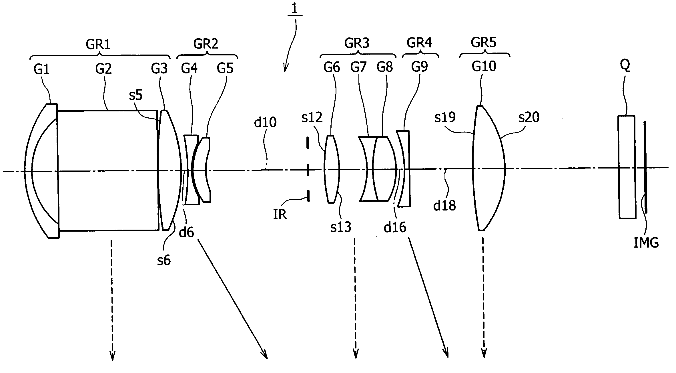
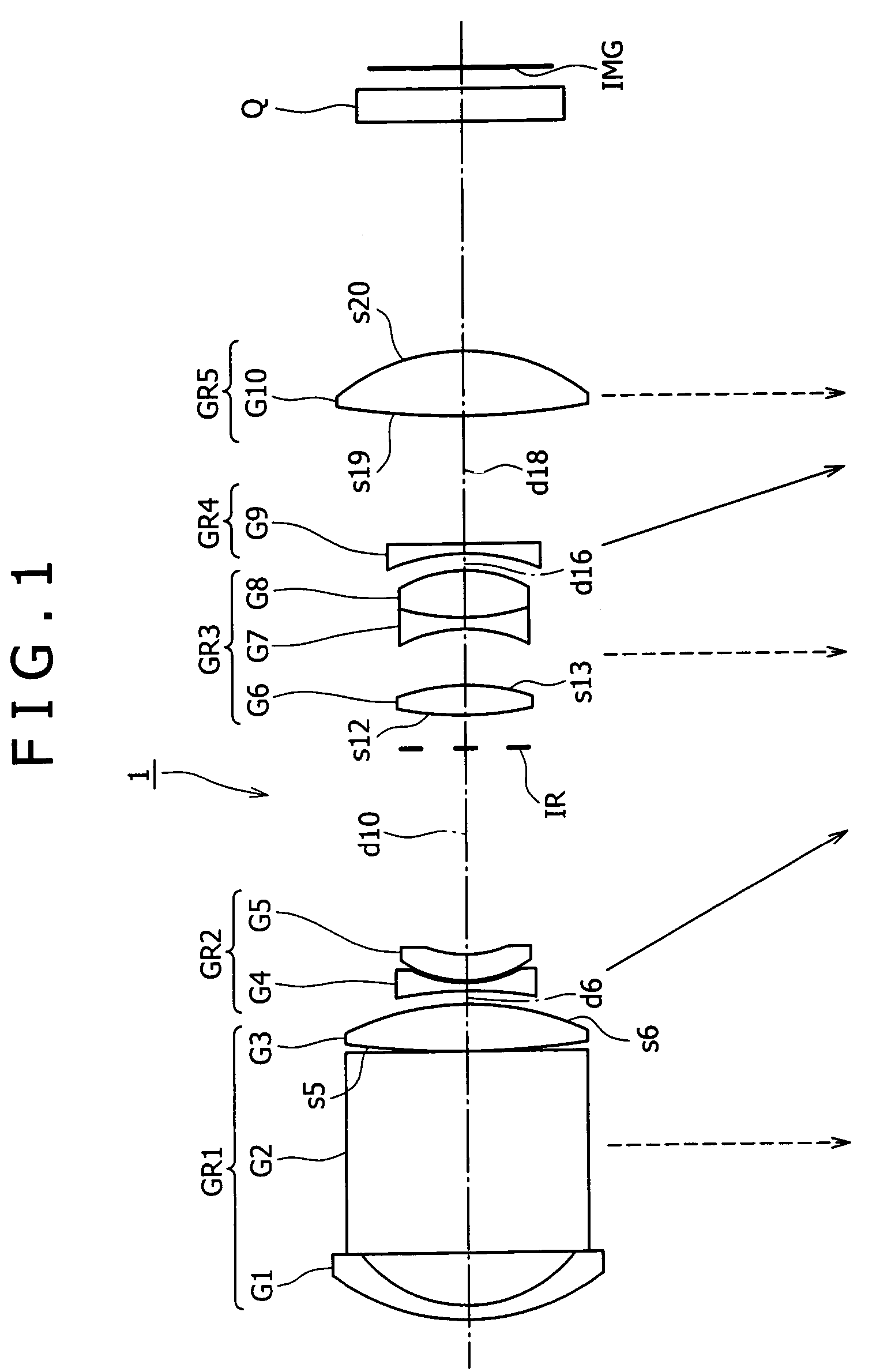
[0052]In the zoom lens 1 the axial distance (air gap) d6 between the first lens group GR1 and the second lens group GR2, the axial distance (air gap) d10 between the second lens group GR3 and the iris aperture IR, the axial distance (air gap) d16 between the third lens group GR3 and the fourth lens group GR4, and the axial distance (air gap) d18 between the fourth lens group GR4 and the fifth lens group GR5 change during zooming. Table 2 shows axial distances (air gaps) at the wide-angle end state, an intermediate focal point position between the wide-angle end state and the telescopic end state, and the telescopic end state, f-numbers (FNO), and half angles ω of view. In Table 2, f represents the focal length of the entire lens system.

[0053]

TABLE 2f6.0009.00016.800FNo3.9954.3395.046ω30.98220.23511.078d60.5003.9148.213d108.2134.7990.500d160.7001.9964.649d185.0453.7491.096

[0054]In the zoom lens 1 according to the first embodiment, the opposite surfaces s5, s6 of the second lens G3 o...

second embodiment

[0068]In the zoom lens 2 the axial distance (air gap) d8 between the first lens group GR1 and the second lens group GR2, the axial distance (air gap) d15 between the second lens group GR2 and the third lens group GR3, the axial distance (air gap) d21 between the third lens group GR3 and the fourth lens group GR4, and the axial distance (air gap) d23 between the fourth lens group GR4 and the fifth lens group GR5 change during zooming. Table 5 shows axial distances (air gaps) at the wide-angle end state, an intermediate focal point position between the wide-angle end state and the telescopic end state, and the telescopic end state, F-numbers FNO, and half angles ω of view. In Table 5, f represents the focal length of the entire lens system.

[0069]

TABLE 5f6.00015.00042.000FNo3.6064.0464.128ω33.69113.5054.967d80.50011.42021.125d1521.22110.3010.596d214.05911.90616.257d2313.1985.3511.000

[0070]In the zoom lens 2 according to the second embodiment, the opposite surfaces s7, s8 of the third ...

third embodiment

[0078]In the zoom lens 3 the axial distance (air gap) d8 between the first lens group GR1 and the second lens group GR2, the axial distance (air gap) d13 between the second lens group GR2 and the iris aperture IR, the axial distance (air gap) d19 between the third lens group GR3 and the fourth lens group GR4, the axial distance (air gap) d22 between the fourth lens group GR4 and the fifth lens group GR5, and the axial distance (air gap) d24 between the fifth lens group GR5 and a protective filter LPF change during zooming. Table 8 shows axial distances (air gaps) at the wide-angle end state, an intermediate focal point position between the wide-angle end state and the telescopic end state, and the telescopic end state, F-numbers FNO, and half angles ω of view. In Table 8, f represents the focal length of the entire lens system.

[0079]

TABLE 8f6.89912.76033.696FNo3.6003.7173.939ω29.70816.5376.252d80.6585.50811.14048d1311.2826.4330.800d191.3903.2206.948d228.6693.8592.000d242.0004.9803....


PUM


Abstract

A zoom lens has good optical performance, is compact, and has a high magnifying power, and is suitable for use in a video camera, a digital still camera, a cellular phone, or the like, and an image pickup apparatus employs the zoom lens. The zoom lens includes a first lens group fixed upon zooming and having a positive refractive power, a second lens group having a negative refractive power, a third lens group having a positive refractive power, a fourth lens group having a negative refractive power, and a fifth lens group having a positive refractive power, which are successively arranged in the order from the object side. At least the second lens group and the fourth lens group are moved for zooming.

Description

TECHNICAL FIELD[0001]The present invention relates to a novel zoom lens and image pickup apparatus. More specifically, the present invention is concerned with a zoom lens which is compact and has a high variable magnifying power, suitable for use in the imaging optical system of a digital input / output device such as a digital still camera, a digital video camera, a digital camera incorporated in a cellular phone, or the like, and an image pickup apparatus employing such a zoom lens.BACKGROUND ART[0002]In recent years, video cameras and digital still cameras employing solid-state imaging device such as CCDs (Charged Coupled Devices) and CMOS (Complementary Metal-Oxide Semiconductor) devices have been in widespread use. Such image pickup apparatus are required to achieve a higher image quality. In particular, digital still cameras with a large number of pixels need imaging lenses having an excellent focusing capability compatible with solid-state imaging devices with a large number of...

Claims


Application Information

Patent Timeline
Patent Type & Authority Patents(United States)
IPC IPC(8): G02B15/14G02B5/04G02B15/20G02B13/18G02B15/16G02B15/167G02B15/173H04N5/225H04N101/00
CPCG02B13/0065G02B15/173G02B13/009G02B15/145121G02B3/0087G03B17/12H04N23/55
Inventor KURODA, DAISUKEIWASAWA, YOSHITO
Owner SONY CORP
Why Eureka
Try Eureka