Network designing device and computer-readable medium

a network design and computer-readable medium technology, applied in data switching networks, frequency-division multiplexes, instruments, etc., can solve the problems of low possibility that high-quality optical amplifiers will be necessary and achieve optimal design, and achieve accurate installation of regeneration repeaters, easy selection of supplies materials of devices, and easy check of transmission permission/inhibition determination

Inactive Publication Date: 2009-03-17
FUJITSU LTD
View PDF16 Cites 7 Cited by
  • Summary
  • Abstract
  • Description
  • Claims
  • Application Information

AI Technical Summary

Benefits of technology

[0018]As described above, equipment expenses of the entire network vary depending on a place of the node in the linear section in which the regeneration repeater is installed. An optimal state thereof is different depending on the topology and traffic demand information of the communication network, transmission line characteristics, performance and costs of the transmission device, and the like. It is therefore an object of the invention to provide a network designing device which can pursue optimal installation of regeneration repeaters in a particular network while checking signal quality reachability of a path therein.
[0021]Further, according to the first aspect of the invention, the determining unit may be adapted to calculate a Q value indicating characteristics of an optical signal for each assumed path, and determine transmission permission / inhibition based on the Q value. By the adaptation, the user can easily check the transmission permission / inhibition determination based on the Q value, and accurately install the regeneration repeaters.
[0022]Further, according to the first aspect of the invention, the display unit may be adapted to display supplies materials of devices prestored in a database when the user selects the supplies materials of devices through the input unit. By the adaptation, the user can easily select the supplies materials of devices.
[0024]Thus, according to the second aspect of the invention, even when the user does not assign supplies materials or arranging positions of the regeneration repeaters, the regeneration repeater assigning unit automatically executes such assignment. Moreover, even when the user does not investigate propriety of the network designing result based on the result of the transmission permission / inhibition determination, the selecting unit selects one of network designs which are designed according to the plurality of different algorithms based on the predetermined standard. Accordingly, an optimal network design can be obtained without any burdens on the user.

Problems solved by technology

However, optical signal characteristics in an optical transmission system are determined by noise light accumulation which accompanies multistage connection of an optical transmission device, and accumulation of complex physical phenomena such as optical fiber wavelength dispersion, polarized wave dispersion, or non-linear effects.
On the other hand, in FIG. 19, since the first to fourth 3R sections are shorter compared with the first and fourth 3R sections of FIG. 18, there is a low possibility that high-quality optical amplifiers will be necessary.
In other words, for example, even when the number of regenerators in the HUB is designed to be minimum, if numerous high-quality optical amplifiers are necessary in consequence, optimal designing is not achieved.

Method used


Image

  • Network designing device and computer-readable medium
  • Network designing device and computer-readable medium
  • Network designing device and computer-readable medium

Examples


Embodiment Construction

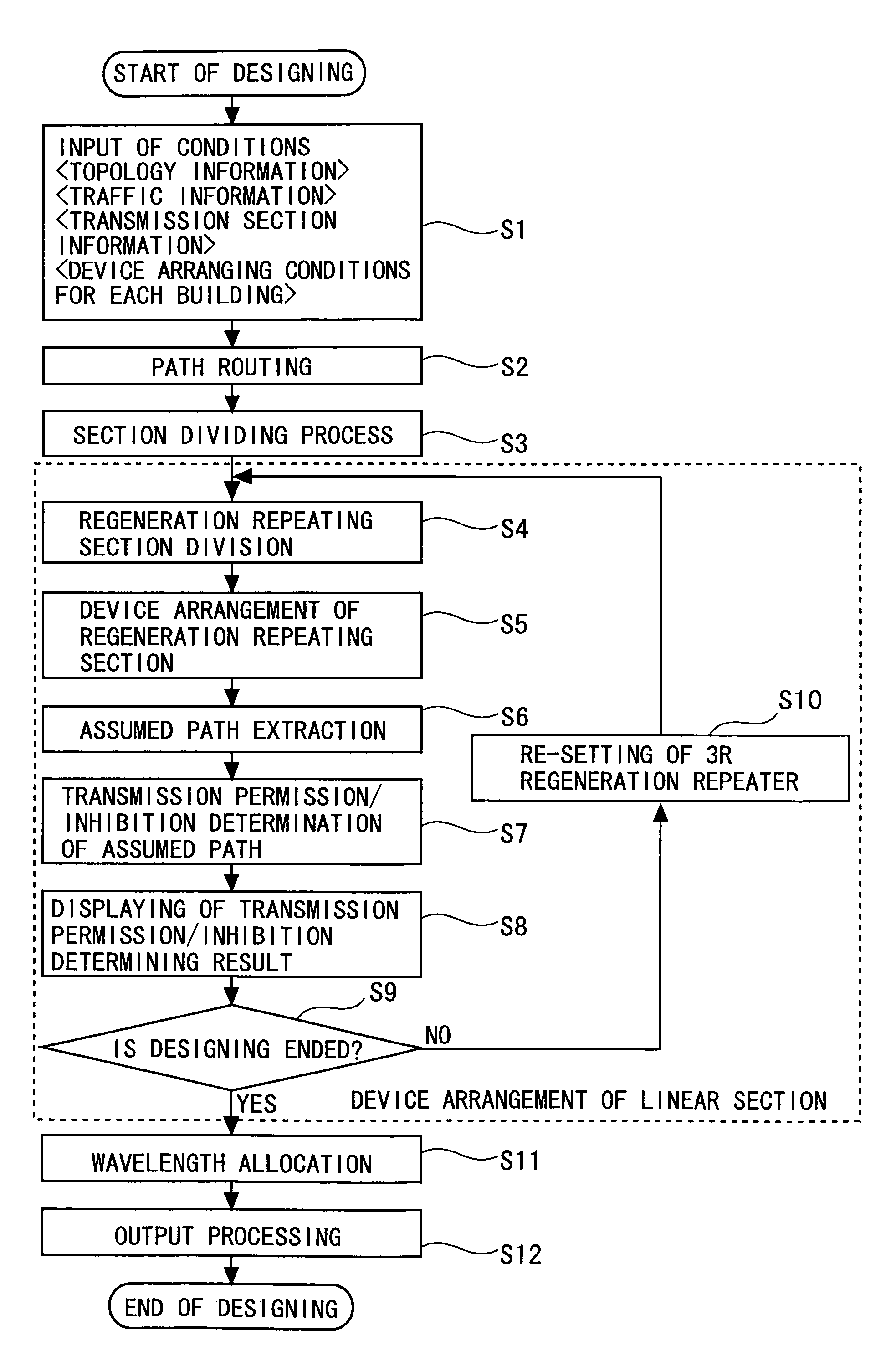
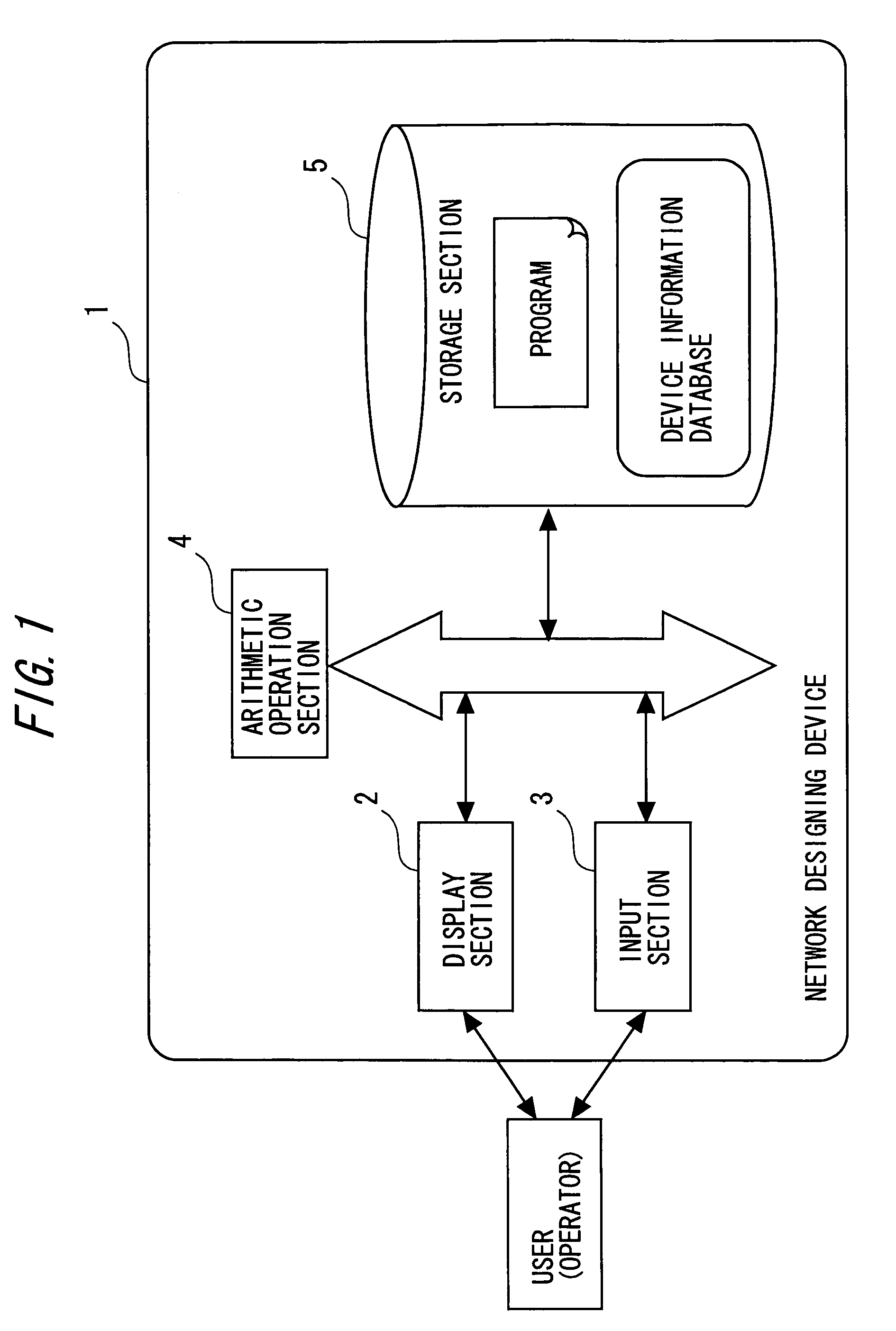
[0046]First, description will be made of a network which is a designing target of a network designing device 1 of the invention. The network to be processed includes a terminal node, a branch node, and a general node. Each node indicates a building. Accordingly, a device to be installed in the building is allocated to each node. In other words, in reality, the device allocated to the node in network designing is arranged in the building.

[0047]The nodes are interconnected via a link. The link indicates a fiber. In other words, in reality, the fiber is installed as the link, and the buildings or the devices therein are interconnected through the fiber to communicate with one another.

[0048]A terminal device is allocated to each terminal node. An HUB is allocated to the branch node. As a result of the network designing, a linear repeater or a regeneration repeater that has a constitution assigned by a user is allocated to the general node.

[0049]Next, a constitutional example of the netw...


PUM


Abstract

Linear networks are divided into a plurality of regeneration repeating sections which have nodes having regeneration repeaters arranged therein at both ends, devices such as linear repeaters or OADMs are arranged at the nodes positioned in the regeneration repeating sections, a plurality of assumed paths assumed as a result of arranging the devices are extracted in the regeneration repeating sections, and transmission permission / inhibition is determined transmission permission / inhibition is displayed to allow a user to perform settings again.

Description

BACKGROUND OF THE INVENTION[0001]The present invention relates to a technology which is effectively applied to a network designing device or a network designing method for supporting optimizing design of an optical communication network.[0002]There is a demand for a technology which enables use of various multimedia services at any time or place. As one of such technologies, a photonic network technology is available, which enables high-speed and inexpensive communication of a large amount of information. Among photonic network technologies, there have been developed a Wavelength Division Multiplexing (WDM) technology which multiplexes and communicates a plurality of optical signals different from one another in wavelength through one optical fiber, and a photonic node technology which constructs a network by regarding each wavelength as one communication path. The development of such technologies has brought about a need to realize a communication network system (hereinafter called...

Claims


Application Information

Patent Timeline
Patent Type & Authority Patents(United States)
IPC IPC(8): H04L12/28H04B10/00H04B10/291H04L12/701H04M3/00
CPCH04L41/145
Inventor NAKASHIMA, HISAOHOSHIDA, TAKESHIAKIYAMA, YUICHITERAHARA, TAKAFUMI
Owner FUJITSU LTD
Why Eureka
Try Eureka