Distributed terminal optical transmission system

a technology of optical transmission system and distribution terminal, which is applied in the field of distributed terminal optical transmission system, can solve the problems of communication service, cost of maintaining multiple sets of optical data networking equipment, and limitations of prior art systems

Active Publication Date: 2009-03-17
PIVOTAL DECISIONS
View PDF104 Cites 32 Cited by
  • Summary
  • Abstract
  • Description
  • Claims
  • Application Information

AI Technical Summary

Benefits of technology

[0007]The present invention provides an architecture and method for transmitting signals over a network which allows for all of lessee's equipment to be located at a extension terminal in lessee's facility. It allows for efficient optical-to-electrical conversions and does not require multiple sets of optical data networking equipment.
[0013]The present invention is an improvement over the prior art because it allows for efficient optical-to-electrical conversions and does not require multiple sets of optical data networking equipment. The present invention provides for coupled metro domain networks which are a part of a larger inter-domain network. The invention facilitates optical signals generated from customer premise equipment (CPE) at the edges of the metro domain networks. The CPEs are connected to extension terminals preferably in lessee's facility. The extension terminals transform the optical signal originating at the CPE into a suitable format for long haul transmission. One or more CPEs may be connected to one or more extension terminals. The optical signal then propagates from an extension terminal to a primary terminal along a metro fiber. At the primary terminal, the optical signal is multiplexed with other optical signals from other extension terminals. The multiplexed signals are then transmitted over LH or ULH network to a second primary terminal via core fiber. The optical signal may propagate along the core fiber with the help of a chain of amplifiers and optical add / drops. The second primary terminal then demuxes the optical signal from other optical signals and transmits the demuxed signal to the proper extension terminal. At the extension terminal, the demuxed optical signal is transformed from its LH format back into a format suitable for inter-connection to a CPE. Using this architecture, the signal under goes optical-to-electrical conversion only at the extension terminals. These extension terminals can be located in lessee's facility. The only equipment located in lessor's facility is the primary terminal containing line amplifiers and add / drop nodes. The transport system meets the networking requirements of intercity connections without the need for complex and costly metro transport gear. Also, the core extension terminals may be physically distributed across several metro network nodes.

Problems solved by technology

Prior art systems suffer from the limitation that a typical communication service provider leasing “space” must provide optical data networking equipment at their own local facilities and must also provide optical data networking equipment at the lessor's facility.
In addition to the cost of maintaining multiple sets of optical data networking equipment, there is an additional penalty from the requirement to use metro transmission systems to connect the lessee communication system provider's facility to the lessor communication service provider's facility and then to use the LH and ULH optical data networking equipment to traverse the LH and ULH optical network.
This system results in excessive optical-to-electrical conversions and increases the operational complexity of the overall systems.
In addition, prior art systems suffer from the requirement to convert customer premise equipment signals into short haul format for transport to a facility, usually a lessor's, and then at the facility, to be converted into a LH format for transport over a LH network.
However, Alexander is intended to provide compatibility with existing systems and does not disclose or suggest a system that allows for efficient optical-to-electrical conversions or one that would locate all terminal equipment in the lessee's facility.
While Van Driel does utilize subcarrier multiplexing, only two wavelengths are involved and the multiplexing is therefore limited.
Van Driel does not disclose transmitting the signals over a LH network.
Nor does Van Driel disclose or suggest a system that allows for efficient optical-to-electrical conversions or one that would locate all terminal equipment in the lessee's facility.

Method used


Image

  • Distributed terminal optical transmission system
  • Distributed terminal optical transmission system
  • Distributed terminal optical transmission system

Examples


Embodiment Construction

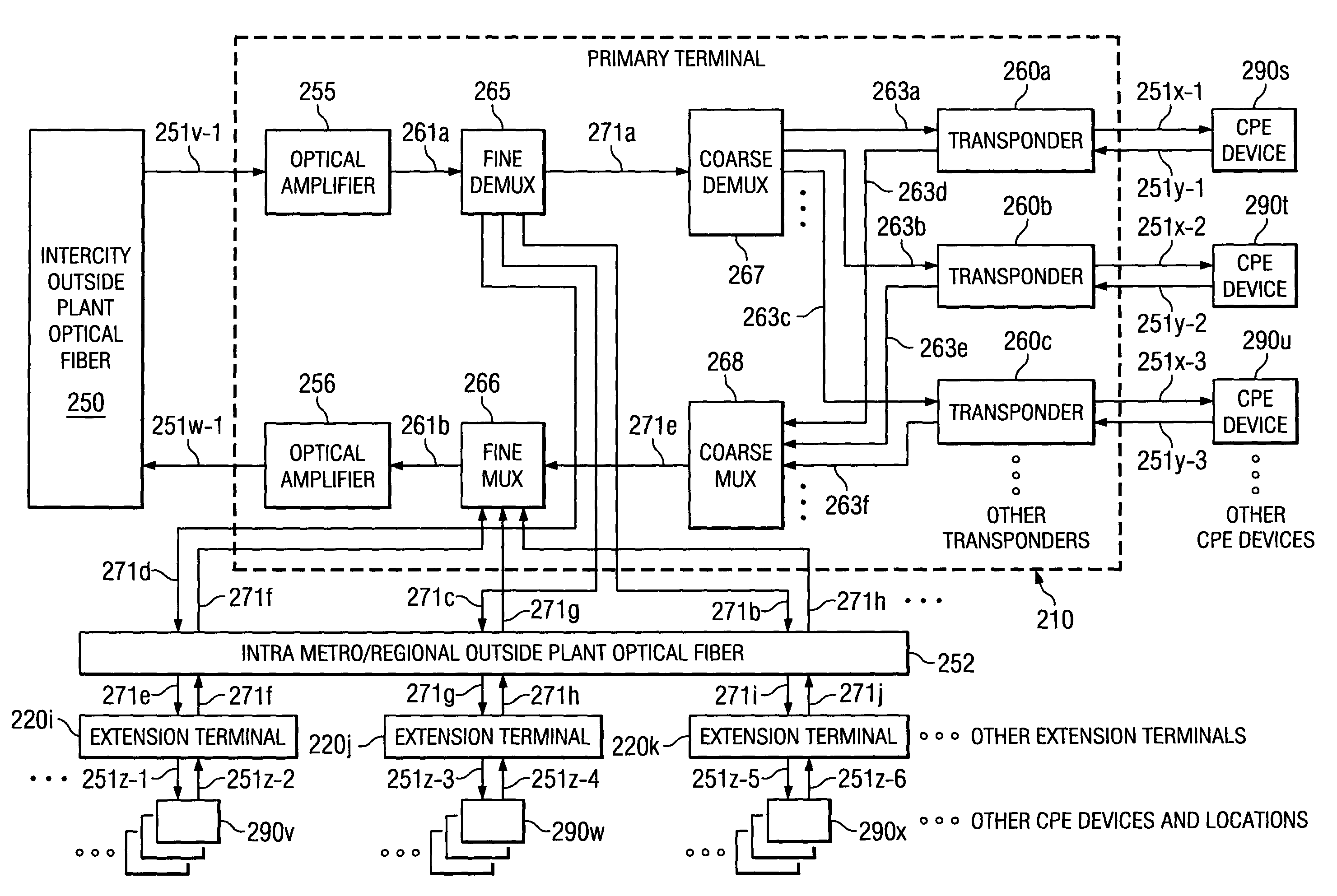
[0028]In the descriptions that follow, like parts are marked throughout the specification and drawings with the same numerals, respectively. The drawing figures are not necessarily drawn to scale and certain figures may be shown in exaggerated or generalized form in the interest of clarity and conciseness. Reference of an A-Z signal or direction means from the left side of the drawing to the right side of the drawing while Z-A means from the right side to the left side. The A-Z or Z-A designation is used for illustrative purposes only.

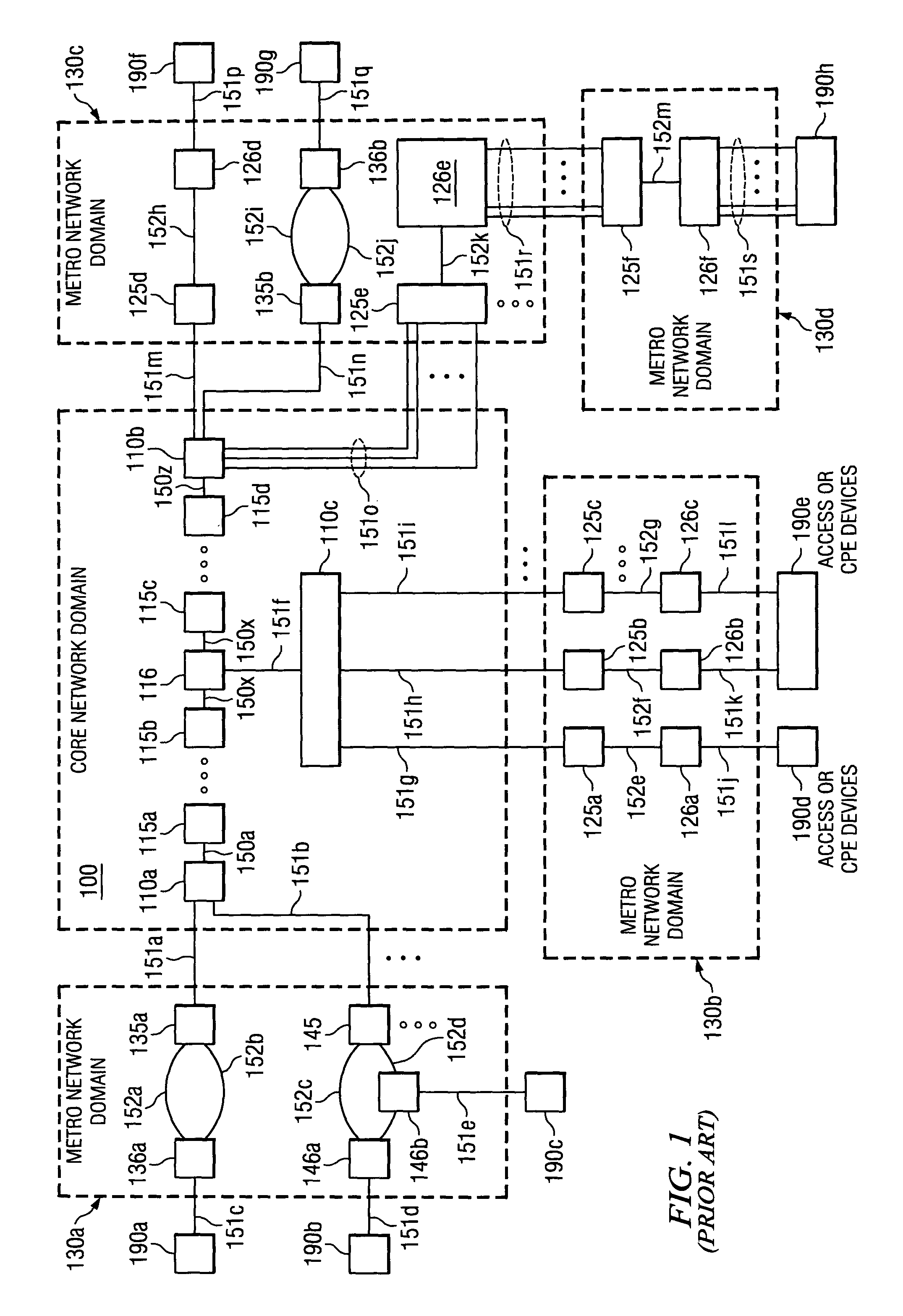
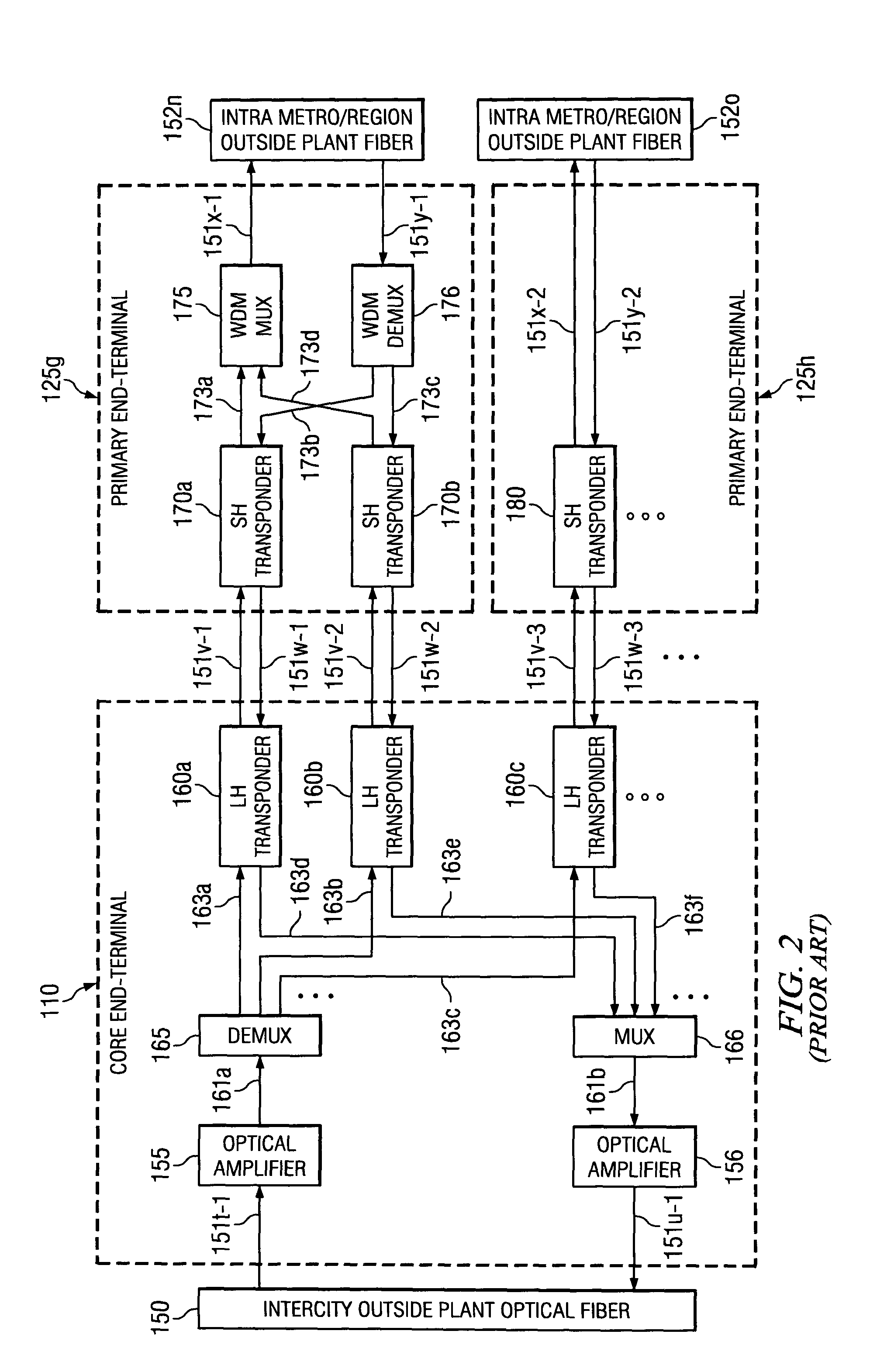
[0029]The prior art as it relates to optical transport networking between domains is shown in FIG. 1 and FIG. 2. Referring to FIG. 1, an optical transport network may be composed of several domains: a core network 100 with a geographic extent of typically between 100 km and 1500 km and a plurality of metro network domains 130a-d with geographic extents typically of 3 km to 100 km.

[0030]Customer premise equipment (CPE) 190a-h are considered to be outsid...


PUM


Abstract

The invention facilitates optical signals generated from customer premise equipment (CPE) at the edges of the metro domain networks. The CPEs are connected to extension terminals that transform the optical signal originating at the CPE into a suitable format for long haul transmission. The optical signal then propagates to a primary terminal where the signal is multiplexed with other optical signals from other extension terminals. The multiplexed signals are then transmitted over LH or ULH network to a second primary terminal where the signal is then demultiplexed from other optical signals and transmited to the proper extension terminal. At the extension terminal, the demultiplexed optical signal is transformed from its LH format back into a format suitable for inter-connection to a CPE. Using this architecture, the signal under goes optical-to-electrical conversion only at the extension terminals or end points. These end points can be located in lessee's facility. The only equipment located in lessor's facility is the primary terminal containing line amplifiers and add / drop nodes.

Description

CROSS-REFERENCE TO RELATED APPLICATIONS[0001]This application claims priority to Provisional Application Ser. No. 60 / 368,545, entitled “Distributed Terminal Optical Network”, by Jaggi, et al., filed Mar. 29, 2002.FIELD OF THE INVENTION[0002]This invention relates to a computer system for transporting optical signals between coupled metro domains using an optical transport networking system and more particularly using a lessor's optical transport networking system to transport a lessee's signal.BACKGROUND OF THE INVENTION[0003]The transmission, routing and dissemination of information has occurred over computer networks for many years via standard electronic communication lines. These communication lines are effective, but place limits on the amount of information being transmitted and the speed of the transmission. With the advent of light-wave technology, a large amount of information is capable of being transmitted, routed and disseminated across great distances at a high rate ove...

Claims


Application Information

Patent Timeline
Patent Type & Authority Patents(United States)
IPC IPC(8): H04J14/02H04B10/24
CPCH04B10/2503H04J14/02H04J14/0226H04J14/0282H04J14/0283H04J14/0286H04J14/0232H04J14/0246H04J14/025H04J14/028H04J2014/0253H04B10/2589
Inventor JAGGI, PAWANYOUNG, MARVIN R.BRAGG, WILLIAM DAVID
Owner PIVOTAL DECISIONS
Why Eureka
Try Eureka