Utility vehicle and assembly of engine and transmission for utility vehicle

a technology for utility vehicles and transmissions, which is applied in the direction of gearing, cycle equipments, hoisting equipments, etc., can solve problems such as errors in center distance, and achieve the effect of accurately fixing and facilitating engine mounting operation

Active Publication Date: 2009-03-24
KAWASAKI MOTORS LTD
View PDF8 Cites 37 Cited by
  • Summary
  • Abstract
  • Description
  • Claims
  • Application Information

AI Technical Summary

Benefits of technology

[0009]The present invention addresses the above described conditions, and an object of the present invention is to provide an assembly of an engine and a transmission that facilitates a mounting operation of the engine and the transmission, and allows a positional relationship between the engine and the transmission to be accurately fixed, both in an axial direction of the engine and the transmission, and in a direction of a straight line connecting an output shaft of the engine to an input shaft of the transmission.
[0011]In the above construction, with the coupling element fitted to the fitting portion of the engine and the fitting portion of the transmission, a positional relationship between the output shaft of the engine and the input shaft of the transmission is accurately fixed. In other words, the engine and the transmission are positioned in a direction of a straight line connecting these shafts to each other. This may eliminate a jig to assemble these components. It shall be understood that the fitting portions are not necessarily concentric with the output shaft and the input shaft.
[0014]The first contact face portion and the second contact face portion may form one flat plane. The first flat face portion may be perpendicular to the output shaft and the second flat face portion may be perpendicular to the input shaft. This allows the contact face portions of the coupling plate to be present on the same flat plane. As a result, the coupling element may be manufactured easily and an assembly operation is facilitated.
[0016]The first fitting portion may form an outer peripheral surface of a part of a cylinder which is concentric with the output shaft, and the second fitting portion may form an outer peripheral surface of a part of a cylinder which is concentric with the input shaft. Thereby, the fitting portions may be easily formed.
[0018]The coupling element may be shaped to be substantially symmetric with respect to a straight line connecting a center of the output shaft to a center of the input shaft as viewed from an axial direction of the output shaft and the input shaft, with the coupling plate fitted to the first and second fitting portions. This makes it possible to increase the strength of the coupling element and to position the engine and the transmission with higher precision.

Problems solved by technology

This may cause an error in the center distance.

Method used


Image

  • Utility vehicle and assembly of engine and transmission for utility vehicle
  • Utility vehicle and assembly of engine and transmission for utility vehicle
  • Utility vehicle and assembly of engine and transmission for utility vehicle

Examples


Embodiment Construction

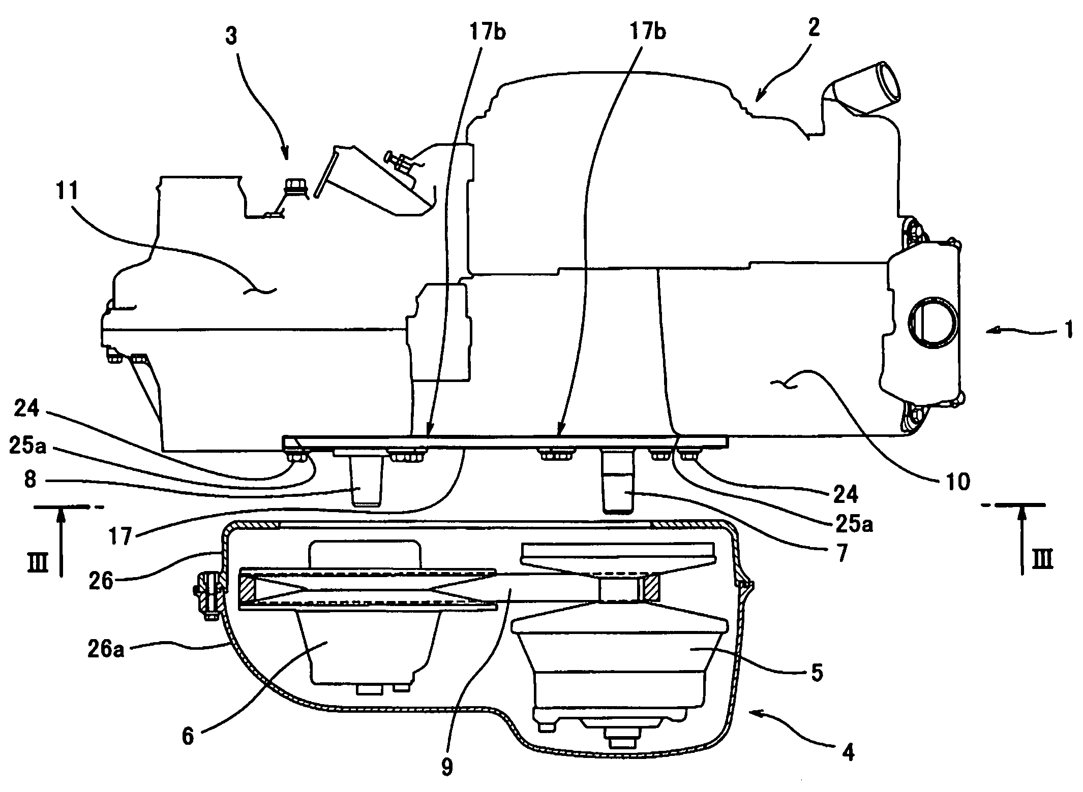
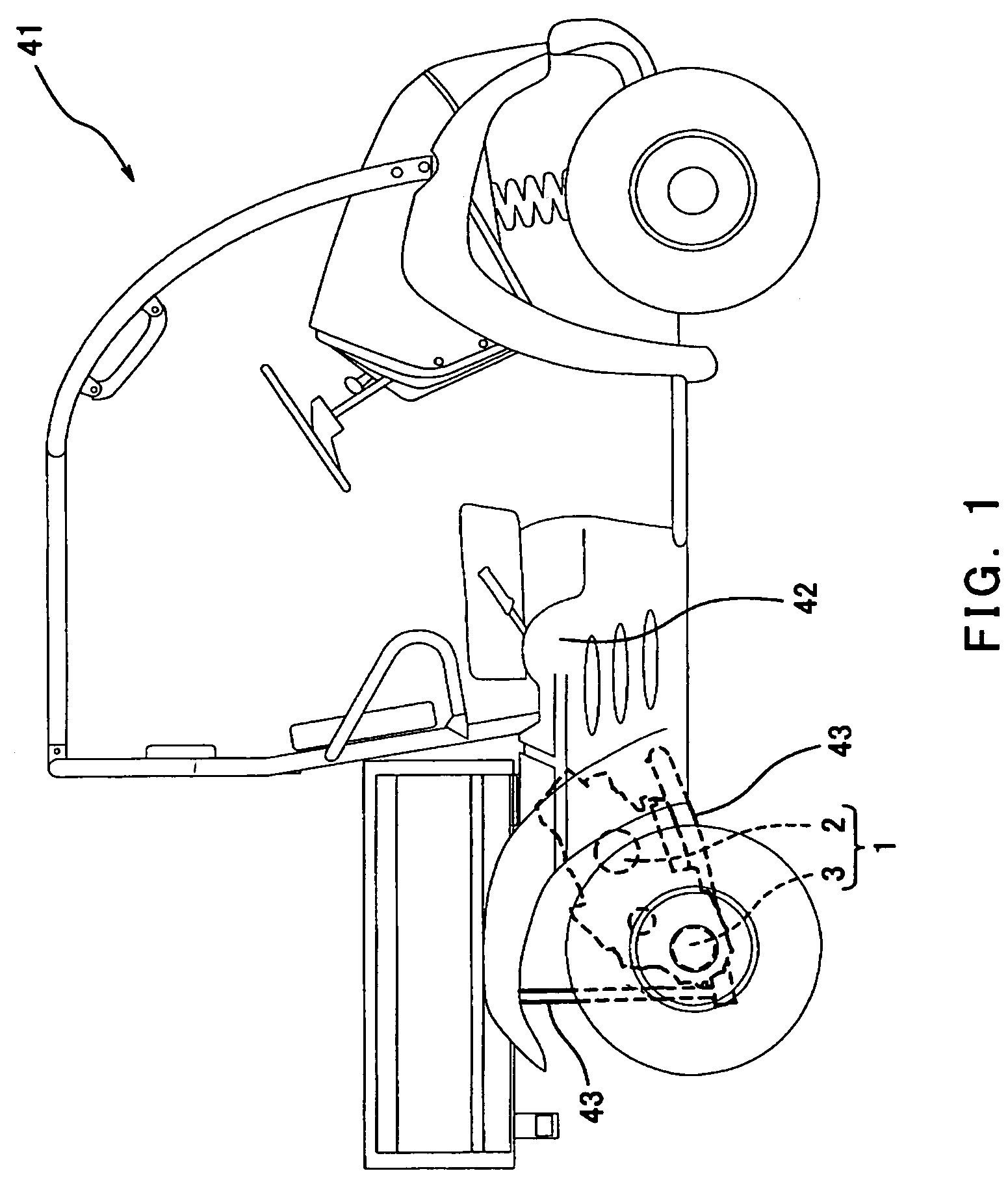
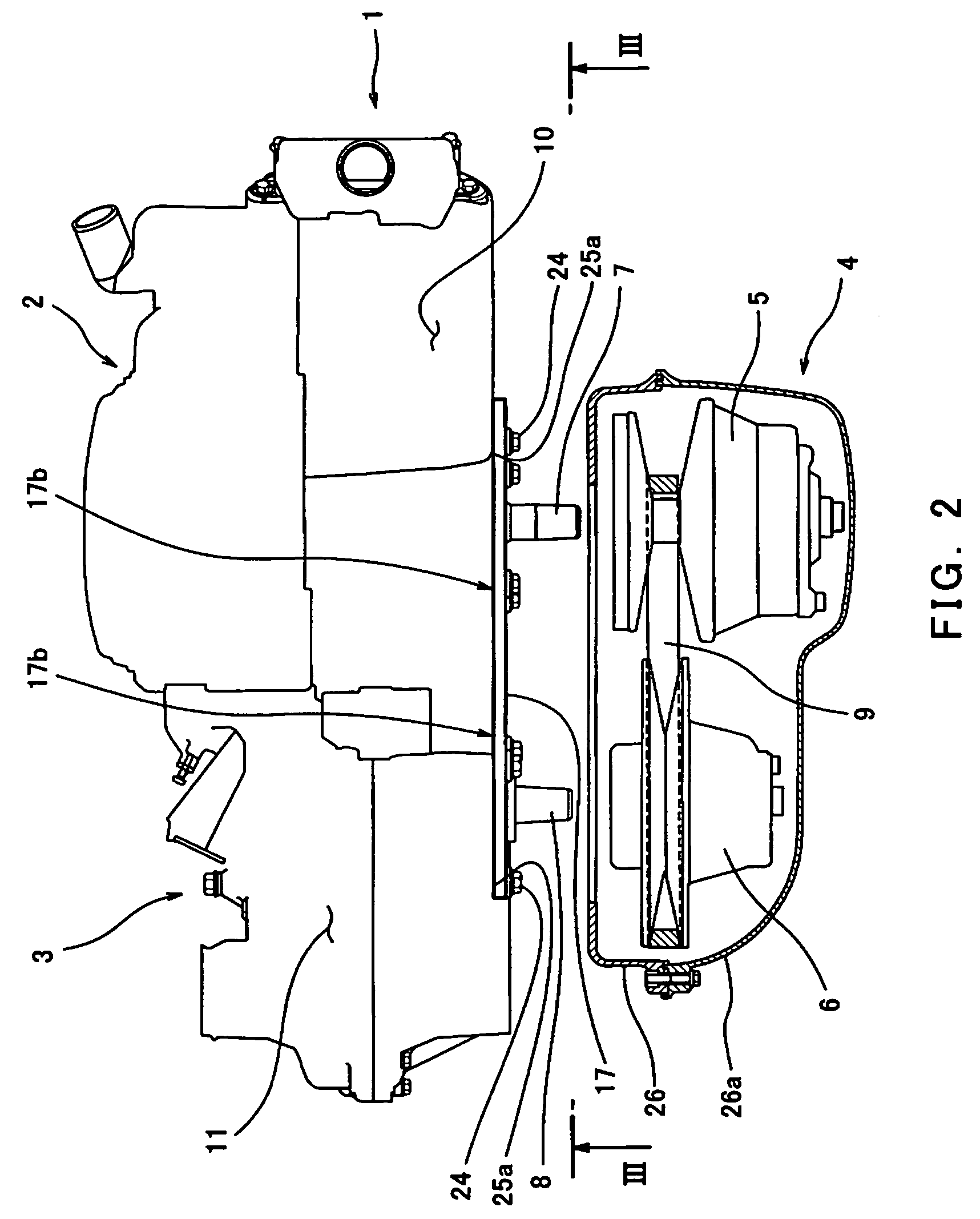
[0028]FIG. 1 shows a lightweight utility vehicle 41 equipped with an assembly 1 of an engine 2 and a transmission 3. The utility vehicle 41 includes a sub-frame 43 that is mounted to a vehicle body 42 so as to be pivotable in a vertical direction and is configured to support rear wheels on a lower side of a rear portion of a vehicle body 42. The assembly 1 including the engine 2 and the transmission 3 is mounted to the sub-frame 43 (see FIGS. 1 and 3). As shown in FIG. 2, a belt converter 4 is mounted to the assembly 1. The belt converter 4 includes a drive pulley 5 coupled to an output shaft 7 of the engine 2 and a driven pulley 6 coupled to an input shaft 8 of the transmission 3. An endless V belt 9 is installed around the pulleys 5 and 6. The belt converter 4 is housed in a belt converter case 26 which is openably covered with a case cover 26a. By opening the case cover 26a, the belt converter 4 becomes accessible.

[0029]A crankcase 10 of the engine 2 and a housing 11 of the trans...


PUM


Abstract

An assembly of an engine and a transmission is disclosed. An output shaft of the engine and an input shaft of the transmission extends in parallel to protrude from the assembly. The assembly typically comprises a first fitting portion that is formed in a crankcase of the engine and is configured to surround the output shaft, a second fitting portion that is formed in a housing of the transmission and is configured to surround the input shaft, and a coupling element having a first opening fitted to the first fitting portion and a second opening fitted to the second fitting portion. A center distance between the output shaft and the input shaft is fixed with the coupling element fitted to the first and second fitting portions.

Description

BACKGROUND OF THE INVENTION[0001]1. Technical Field[0002]The present invention generally relates to an assembly of an engine and a transmission, and a utility vehicle equipped with the assembly. More particularly, the present invention relates to an assembly of an engine and a transmission that is mounted in vehicles such as two-wheel-drive utility vehicles and four-wheel-drive utility vehicles, and a utility vehicle equipped with the assembly.[0003]2. Description of the Related Art[0004]Conventionally, it has been known that a reinforcing element is used to provide a firm coupling between an engine and a transmission (see Japanese Laid-Open Patent Application No. Hei. 8-61469). The reinforcing element, for example, a stiffener, is mounted to provide firm coupling between the engine and the transmission, which are coupled to each other.[0005]In some vehicles, the engine and the transmission are mounted in an uncoupled state to a frame of a vehicle body, because a distance between th...

Claims


Application Information

Patent Timeline
Patent Type & Authority Patents(United States)
IPC IPC(8): B60K17/22B60K17/06F16H57/02F16H57/035
CPCF16H9/18F16H57/022F16H57/025F16H57/035B60K5/00B60K17/00F16H2057/0203F16H2057/02056
Inventor MORITA, TAISUKEFUJIMOTO, HIROYUKI
Owner KAWASAKI MOTORS LTD
Why Eureka
Try Eureka