Local area network contention avoidance

a local area network and avoidance technology, applied in the field of local area network avoidance, can solve the problems of packet loss, network impairment, network resources may be oversubscribed, etc., and achieve the effect of avoiding contention on the lan and removing contention among local transmitters

Active Publication Date: 2009-03-24
RIVULET COMM INC
View PDF81 Cites 3 Cited by
  • Summary
  • Abstract
  • Description
  • Claims
  • Application Information

AI Technical Summary

Benefits of technology

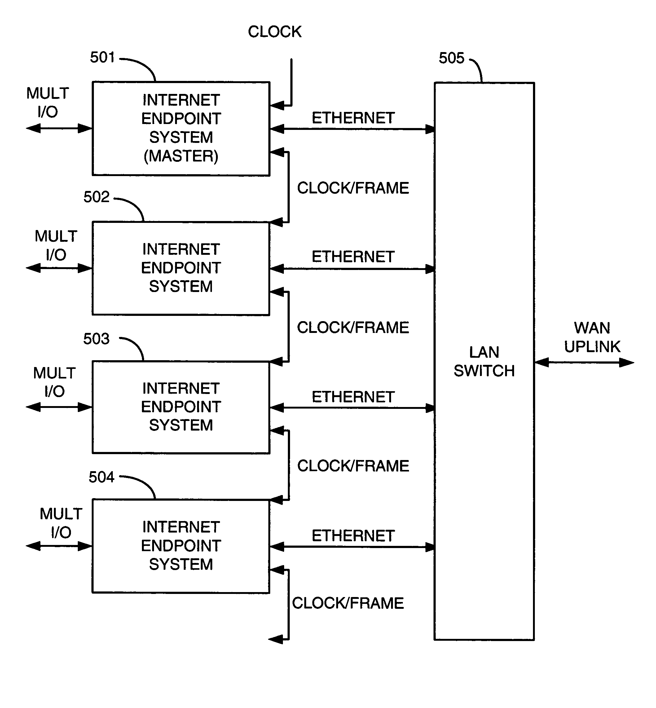
[0009]The invention provides a method for transmitting packets in a network by eliminating contention among local transmitters in the network. A device comprises a CPU and other components that accept input from various transmitting data sources. The device processes signals from the various transmitting sources and converts these signals to packets, before they are output via a LAN and / or WAN interface, thus avoiding contention on the LAN, since only one device produces the packets from many signal sources. This device may initiate and receive connections via the WAN and begin transmitting over the Ethernet to the WAN at agreed-upon rates, without contention.

Problems solved by technology

If they do, then network resources may be oversubscribed.
When this happens, data may be delayed or lost, resulting in network impairment.
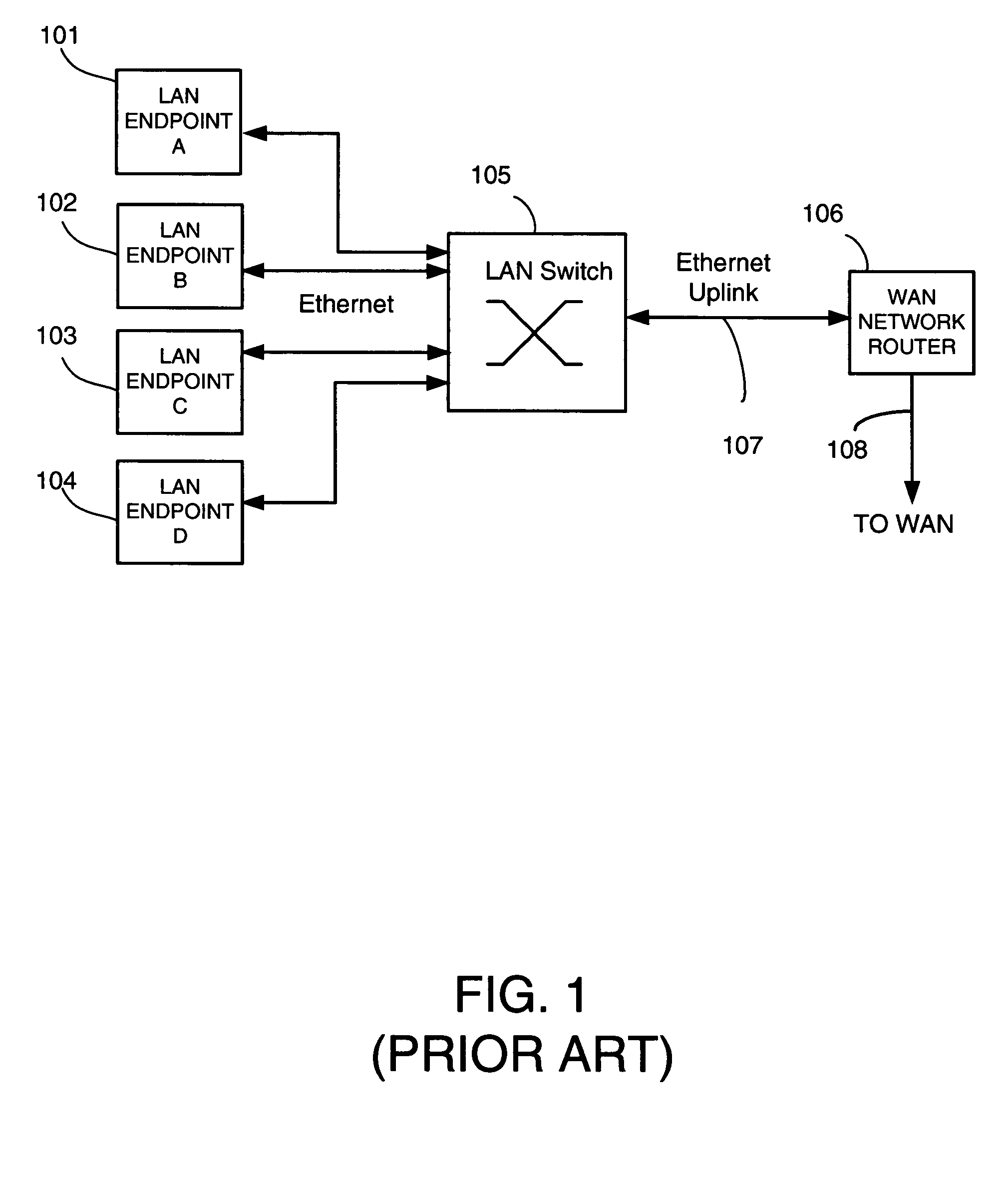
If too many packets are simultaneously transmitted by the other endpoints to LAN switch 105, LAN switch 105 may have a queue overflow, causing packets to be lost.
Similarly, WAN router 106 may have a queue overflow, causing packets to be lost at that point.
The net result is that congestion due to contention among local transmitters causes data to be lost.
This is typically caused by an internal queue in the devices becoming full and thus becoming unable to accept new packets until the outgoing packets have been removed from the queue.
This creates a problem in that transmitting endpoints cannot be guaranteed that their packets will arrive, necessitating other solutions such as the use of guaranteed-delivery protocols such as Transmission Control Protocol (TCP).
Such solutions may be inappropriate for broadcast video, voice over IP or other realtime applications, which cannot wait for retransmission of packets.
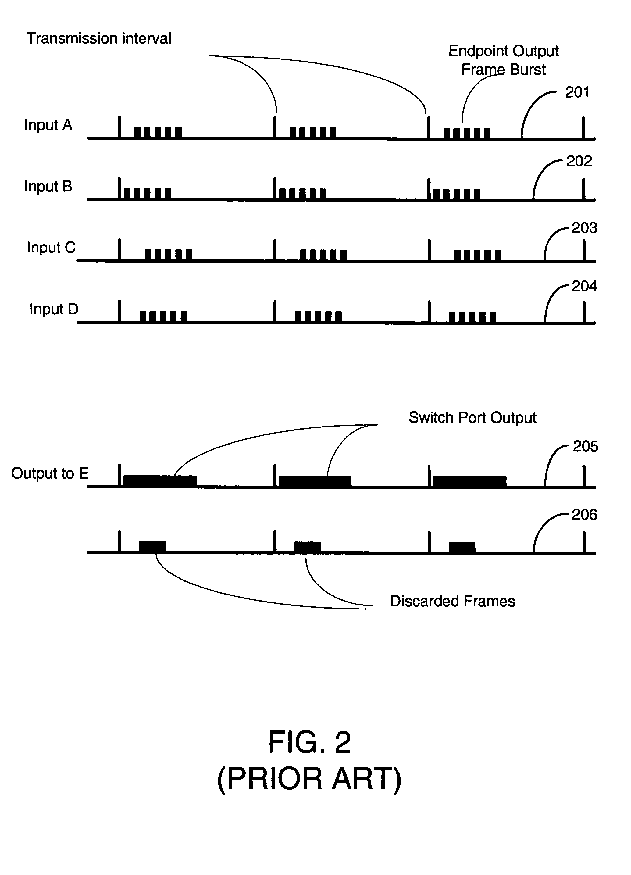
However, because of the coincidental timing of the packet bursts on Input A through Input D, the Ethernet switch is oversubscribed.

Method used


Image

  • Local area network contention avoidance
  • Local area network contention avoidance
  • Local area network contention avoidance

Examples


Embodiment Construction

[0017]FIG. 3 shows one possible device for carrying out various principles of the present invention. The device 301 comprises a backplane bus 307 and a CPU 302 that coordinates the scheduling and other activities of the device. CPU 302 may comprise, for example, an IBM 440GX processor. The CPU includes or is coupled to a local area network, such as an Ethernet via an Ethernet interface that outputs Internet Protocol packets encapsulated in Ethernet frames, as is conventional. The Ethernet interface may for example comprise a gigabit Ethernet. Other network interfaces are possible, such as a telecommunication interface, or any type of packet interface. The packet network interface may be coupled to a WAN router 313 for transmission and reception over a Wide Area Network (WAN), such as the Internet. In another embodiment, device 301 may be directly coupled to WAN network router 313 rather than being connected through device 314. In yet another embodiment, device 301 may be directly co...


PUM


Abstract

The invention provides a method for transmitting packets in a network from multiple data sources, by eliminating contention among local transmitters in the network. A device comprises a CPU and other modules that accept input from various signal sources. The device processes the signals from the various sources, converts the signals to data and then outputs the signal data in the form of packets which it sends via a LAN and / or WAN, thus avoiding contention on the LAN. The invention may initiate and receive connections via the LAN or WAN and begin transmitting over the LAN or WAN at agreed-upon rates without contention.

Description

BACKGROUND OF THE INVENTION[0001]The present invention relates generally to a system for reducing packet congestion for multiple devices that need to communicate over a network, such as the Internet. The subject matter of this application is related to my previously-filed U.S. application Ser. No. 10 / 697,103, now U.S. Pat. No. 7,339,923, entitled “Endpoint Packet Scheduling System,” filed on Oct. 31, 2003.[0002]Ethernet and packet-switched Internet Protocol (IP) networks are systems for transmitting data between different points. These systems are known as “contention-based” systems. That is, all transmitters contend for network resources. All transmitters may transmit simultaneously. If they do, then network resources may be oversubscribed. When this happens, data may be delayed or lost, resulting in network impairment.[0003]As shown in FIG. 1, a conventional network comprises a plurality of Local Area Network (LAN) endpoints, such as computers connected to an Ethernet LAN. The end...

Claims


Application Information

Patent Timeline
Patent Type & Authority Patents(United States)
IPC IPC(8): H04L12/28H04L12/56G01R31/08G06FG06F11/00G06F15/16G08C15/00H04J1/16H04L1/00H04L12/26H04L12/46
CPCH04L12/4625H04L47/10H04L47/125
Inventor ROGERS, STEVEN A
Owner RIVULET COMM INC
Why Eureka
Try Eureka