IrDA transceiver module that also functions as remote control IR transmitter

a technology of irda transceiver and transmitter, which is applied in the field of irda transceivers, can solve the problems of adding cost to the system, reducing the overall system cost, size and power consumption, and unable to provide the coding information of the remote control manufacturer independently of the hardwar

Inactive Publication Date: 2009-03-24
IXYS INTL LTD
View PDF24 Cites 8 Cited by
  • Summary
  • Abstract
  • Description
  • Claims
  • Application Information

AI Technical Summary

Benefits of technology

[0012]Rather than providing a first infrared LED that has a peak emission suited for IrDA communication and a second infrared LED that has a peak emission suited for remote control (RC) communication, a single IrDA LED having a peak emission suited for IrDA communication (for example, 875 nm) is used to transmit both an IrDA transmission as well as an RC transmission. By using a single infrared LED for both IrDA and RC transmission purposes, the field effect transistor (FET) of the prior art solution of FIG. 4 is omitted. RC codeset information is made available to the central processing unit (CPU) of the device of which the IrDA module is a part, thereby allowing the CPU to generate RC signals. This eliminates the need for the separate microcontroller of the prior art solution of FIG. 4 and further reduces overall system cost, size and power consumption.

Problems solved by technology

The remote control manufacturer evidently will not provide the PDA manufacturer the coding information independently of hardware.
Providing the two transmitter diodes into the form factor is difficult even without increasing the die size of controller die 5.
Providing this IR LED die adds cost to the system.
In addition, IrDA module assembly can be more expensive because the placement of the two IR LEDs is somewhat difficult.
Due to the mismatch, however, it may be necessary for the IrDA transmitter LED power to be increased in order for it to work properly in a remote control application.

Method used


Image

  • IrDA transceiver module that also functions as remote control IR transmitter
  • IrDA transceiver module that also functions as remote control IR transmitter
  • IrDA transceiver module that also functions as remote control IR transmitter

Examples


Embodiment Construction

[0026]Reference will now be made in detail to some embodiments of the invention, examples of which are illustrated in the accompanying drawings.

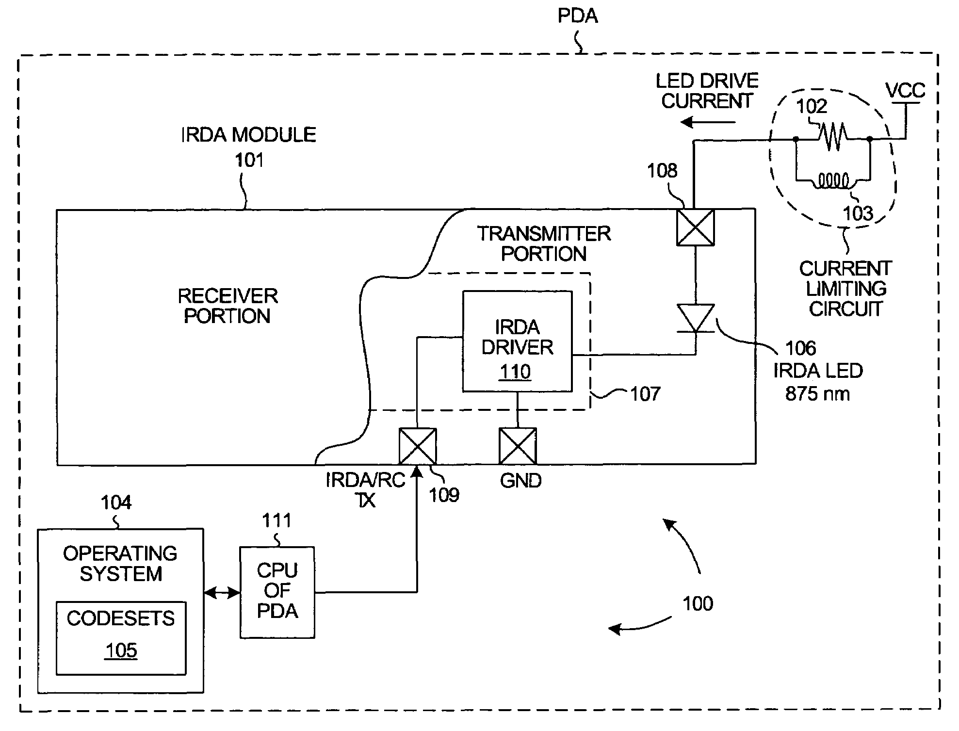
[0027]FIG. 5 is a diagram of a system 100 in accordance with one embodiment of the invention. System 100 includes an IrDA transceiver module 101, a current-limiting resistor 102, an inductor 103, a central processing unit (CPU) 111, and an operating system 104 that has access to IR remote control (RC) codeset information 105. Rather than providing two LED transmitter diode dice of different wavelengths in IrDA module 101, only one 875 nm transmitter LED diode die 106 is provided. IrDA module 101 includes the 875 nm transmitter LED diode die 106, a controller die 107, and an IrDA receiver PIN diode die (not shown). IrDa module 101 is of standard IrDA module construction and includes a molded plastic transmitter lens disposed over the IrDA transmitter diode 106 and another receiver lens disposed over the IrDA receiver diode. IrDA module 101 ma...


PUM


Abstract

The infrared LED of an IrDA module transmits IR energy with a peak wavelength (for example, 875 nm) appropriate for IrDA communication. This peak wavelength is lower than is the wavelength (for example, 940 nm) used in ordinary IR remote controls (RC). The IrDA LED does, however, transmit some energy at the wavelength of the peak sensitivity of an RC receiver. When making an IrDA transmission, the IrDA LED is driven with a lower amount of current. When making an RC transmission, the IrDA LED is driven with an increased amount of current such that higher wavelength emissions received by the RC receiver are of adequate power to realize RC communication. A passive circuit is disclosed for automatically increasing IrDA LED current during RC transmissions. The circuit involves an inductor that shunts current around a current-limiting resistor used to limit LED drive current.

Description

TECHNICAL FIELD[0001]The present invention relates generally to IrDA transceivers.BACKGROUND INFORMATION[0002]Personal digital assistants (PDAs), cell phones, digital cameras, laptop computers and other portable electronic devices often use a type of infrared transceiver called an IrDA (Infrared Data Association) transceiver to transfer information. FIG. 1 illustrates a typical IrDA transceiver 1. Transceiver 1 is a multi-chip module that is enclosed in a metal shield 2. FIG. 2 is a cross-sectional view of the IrDA transceiver. FIG. 3 is a top-down cross-sectional view of the circuitry within the IrDA module. The IrDA module includes three dice: 1) an IR transmitter diode die 3, 2) an IR receiver PIN diode die 4, and 3) a controller die 5. The three dice are mounted on a very small circuit board 6. Molded plastic 7 covers the printed circuit board and die assembly and forms two semi-spherical lenses 8 and 9. Lens 8 is to focus incoming IR radiation 10 onto the PIN receiver diode 4. ...

Claims


Application Information

Patent Timeline
Patent Type & Authority Patents(United States)
IPC IPC(8): H04B10/04G08C23/04H04B10/00H04B10/10
CPCG08C23/04H04B10/1143
Inventor GRACE, ALAN
Owner IXYS INTL LTD
Why Eureka
Try Eureka