
Yarn measuring device for flat bed knitting machines

a technology of knitting machine and measuring device, which is applied in the direction of knitting, weft knitting, textiles and paper, etc., to achieve the effect of accurately calculating the total required amount of yarn consumption, improving measuring accuracy, and facilitating fast adjustment of cam position

Inactive Publication Date: 2009-03-31
PAI LUNG MACHINERY MILL CO LTD
View PDF6 Cites 13 Cited by
  • Summary
  • Abstract
  • Description
  • Claims
  • Application Information

AI Technical Summary

Benefits of technology

[0009]Therefore, the primary object of the present invention is to provide a yarn measuring device for flat bed knitting machines that can measure stitches in a bidirectional fashion, improve measuring accuracy, allow direct reading of measured values and facilitate fast adjustment of cam position to accurately calculate total required amount of yarn consumption, improve fabric quality and increase production efficiency.
[0011]The yarn measuring device thus formed provides many benefits, notably:
[0015]4. It allows the cam position to be adjusted quickly and easily during operation.

Problems solved by technology

However, the size of the stitches is difficult to differentiate by people's naked eyes.
1. The conventional yarn measuring device previously discussed can measure only in one direction. The home magnet 26 has to be reset to zero before starting receiving the rotational signal. Based on technical perspective, removing the home magnet 26 or adding another home magnet 26 close to the second magnet 28 still cannot easily perform bidirectional measurement. Without the home magnet 26 resetting to zero, the logic circuit control box 21 will do accumulation endlessly, and a desired measured value cannot be calculated and obtained. But adding the home magnet 26 beyond two ends of the first magnet 27 and second magnet 28, after the sensor 24 has detected the first magnet 27 and the logic circuit control box 21 starts accumulation, and at the instant the sensor 24 also detects the second magnet 28 and accumulation is stopped, the logic circuit control box 21 is reset to zero by the home magnet 26 close to the second magnet 28 before process is started. Hence the process is suspended. As a result, the measuring device has to reset the home magnet 26 to zero before performing each measurement. This one way measurement causes many disadvantages. For instance, the cam on the carriage to drive the needles in the forward movement is different from the one in the backward movement. As the cams have allowances during fabrication, and tolerances also exist during assembly, measurement of yarn consumption during the forward movement can be obtained to adjust the cam, but measurement of the backward movement can not be obtained and adjustment of the cam cannot be done. As a result, different sizes of fabric stitches will be formed.
2. The error range of the measured value of the conventional yarn measuring device is too great. Due to the yarn 17 is fed constantly during operation of the flat bed knitting machine, friction occurs between the circumferential surface of the wheel 19 and the yarn 17, and the yarn 17 drives the wheel 19 rotating. As previously discussed, the yarn consumption can be measured by the rotational times of the wheel 19, the error range of the measure value depends on the circumferential length of frictional contact between the wheel 19 and the yarn 17, or the radius that determines the circumferential length of the wheel 19. As the length of frictional contact between the yarn 17 and the circumference of the wheel 19 is not sufficient, sliding could occur and driving of the wheel 19 could be not possible. In such an occasion, the measured value has little meaning. To prevent such a phenomenon from occurring, the length of frictional contact between the yarn 17 and the circumference of the wheel 19 has to be increased, namely the circumference or radius of the wheel 19 has to be greater. But increasing the circumference of the wheel 19 also makes the error range of the measured value greater. As measurement of yarn consumption is calculated by the rotational times of the wheel 19, when the wheel 19 rotates close to one time but not exactly one time, an error occurs to the measured yarn consumption at that time. In the conventional technique, no matter how much the circumference of the wheel is reduced, the error range of the measured value still is too large. For instance, given a minimum wheel radius of 0.25 cm as a reasonable and practical value, the circumferential length is about 1.57 cm, and the measured value error range is about 0 to 1.56 cm. Namely the maximum error value is about 1.56 cm. With the error value at such a size, the accuracy is not desirable.
3. Reading of the measured value of the conventional yarn measuring device is difficult. As the logic circuit control box 21 is located on the carriage 10, and the display 42 is located on the logic circuit control box 21, reading the process result displayed on the display 42 has to be waited until the carriage 10 has finished moving. It is inconvenient for users.
4. Adjustment of the cams on the conventional yarn measuring device is tedious. As reading of the process result on the logic circuit control box 21 can be done only after the carriage 10 has stopped moving, then the cams can be adjusted in a still manner. After adjustment, the process result can only be obtained by reading the logic circuit control box 21 after the carriage 10 has stopped moving again, then another adjustment of the cams can be made. It is a tedious operation. Such a device that does not allow the process result to be directly read while the carriage is moving and the cams to be adjusted quickly and dynamically cannot meet the present market requirement.

Method used


Image

  • Yarn measuring device for flat bed knitting machines
  • Yarn measuring device for flat bed knitting machines
  • Yarn measuring device for flat bed knitting machines

Examples


Embodiment Construction

[0029]The present invention provides a yarn measuring device and particularly to a yarn measuring device for a flat bed knitting machine.

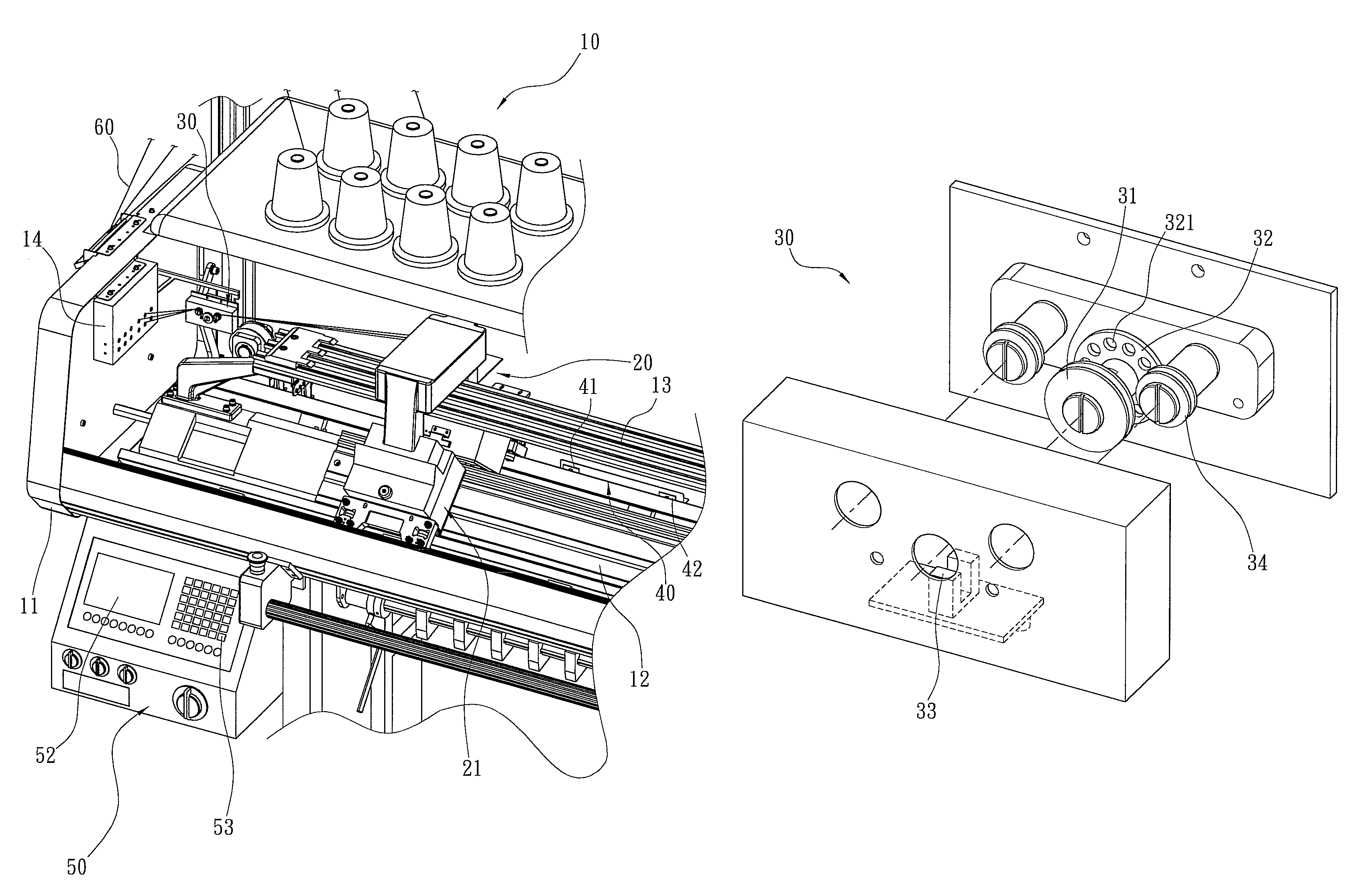
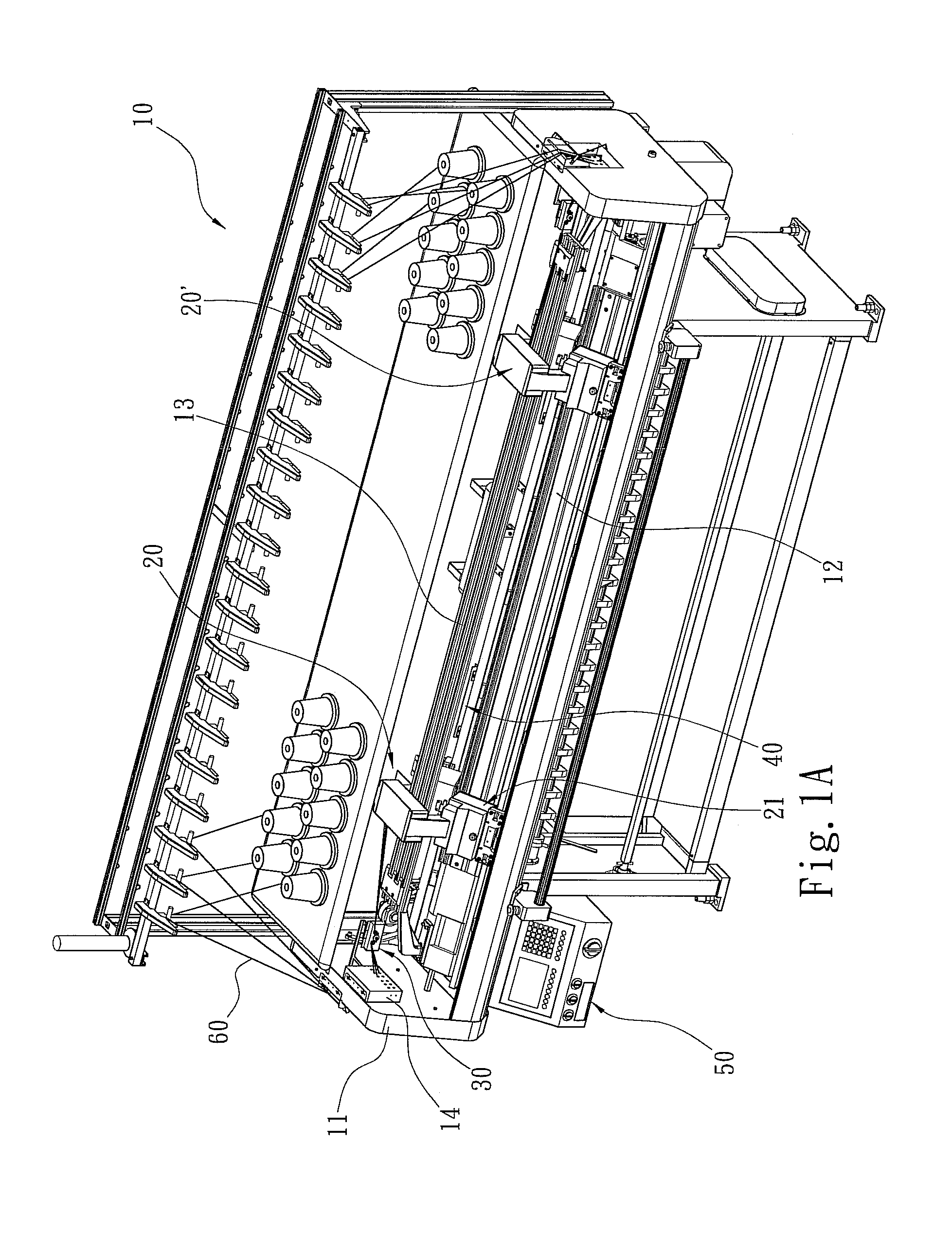
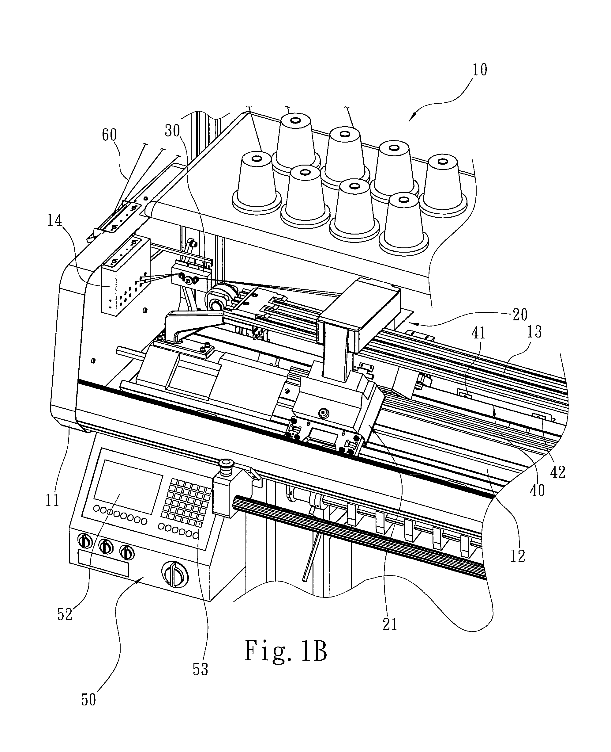
[0030]Referring to FIGS. 1A, 1B, 2, 3, 5 and 6, the flat bed knitting machine 10 has a chassis 11, a needle bed 12 located horizontally on the chassis 11, a track 13 located above the needle bed 12 and in parallel therewith, and a carriage 20 straddled the track 13 and movable horizontally thereon. The carriage 20 has two ends each fastens to a cam controller 21 with cams 211 located thereon, as shown in FIG. 6 in which a plurality of cams are located at a lower side of the cam controller 21, and a mask plate 212 located at one end. The yarn measuring device includes a counter 30 located on the chassis 11 close to a distal end of the track 13. The counter 30 has an axial grating wheel 32 with a plurality of apertures 321 formed thereon in a circular array and equally spaced from one another, and an U-shaped sensor 33. The grating wheel 32 has a pri...


PUM


Abstract

A yarn measuring device for a flat bed knitting machine which has a chassis, a needle bed, a track and a carriage. The carriage has a cam controller and a mask plate. The yarn measuring device includes a counter, a detection unit and a programmable logic circuit controller. The programmable logic circuit controller, the counter, the detection unit, the carriage and the cam controller are electrically interconnected. Knitting stitches can be measured in a bidirectional fashion. Measuring accuracy improves, measured value can be read directly and easier, and the position of cams can be adjusted quickly. Total yarn requirement can be calculated accurately, fabric quality can be improved and production efficiency can be enhanced.

Description

FIELD OF THE INVENTION[0001]The present invention relates to a yarn measuring device and particularly to a yarn measuring device for flat bed knitting machines.BACKGROUND OF THE INVENTION[0002]In textile industry, a key factor to maintain consistent quality of fabrics produced by each flat bed knitting machine is controlling the size of stitches knitted through yarns. The size of the stitches is formed by the amount of the yarns latched by needles. When there is a need to produce a great amount of one type of fabrics, the stitch formed by each flat bed knitting machine must be controlled at the same size whenever possible. In the event that the stitches of fabrics produced by different flat bed knitting machines are different, the cams driving the needles to perform yarn latching operation have to be adjusted. However, the size of the stitches is difficult to differentiate by people's naked eyes. Hence scientific measuring devices are needed to perform the task. Namely, by measuring...

Claims


Application Information

Patent Timeline
Patent Type & Authority Patents(United States)
IPC IPC(8): D04B15/48
CPCD04B35/12
Inventor LIN, YU-SHENGWANG, JOE
Owner PAI LUNG MACHINERY MILL CO LTD
Learn More