Apparatus for comminuting material having a cool air channel

a technology of comminuting material and cool air, which is applied in the direction of gas current separation, solid separation, grain treatment, etc., can solve the problems of increasing the difficulty of conventional device operators, the size of particles and the particle distribution of milled materials are no longer within the desired range, and achieve the effect of increasing the machine efficiency of conventional devices

Active Publication Date: 2009-03-31
PALLMANN MASCHFAB GMBH & CO KG
View PDF4 Cites 35 Cited by
  • Summary
  • Abstract
  • Description
  • Claims
  • Application Information

AI Technical Summary

Benefits of technology

[0014]It is therefore an object of the present invention to increase the machine efficiency of conventional devices without thereby exposing the material to additional thermal stress.
[0015]A first benefit of the invention is that in addition to cooling the milling gap with self-generated air, additional cool air is introduced into the device in accordance with the present invention. The thus increased air volume makes it possible to discharge additional heat so that the comminuting tools and the materials to be milled are exposed to considerably less heat. This allows the improvement of the operational performance, and thus also the cost effectiveness of devices of the present invention.

Problems solved by technology

This is caused by friction and impact forces the materials are subjected to during the comminuting process, and which primarily affect the comminuting tools.
Problems occur on a regular basis, when heat-sensitive materials are to be comminuted.
Especially when plastics with a low melting point are to be comminuted, operators of conventional devices face a difficult task.
If the material-dependent temperature limit is thereby exceeded, the material softens and begins to melt with the result that individual particles bake together such that the size of the particles and the particle distribution of the milled material are no longer within the desired range.
On the other hand, the overheated particles bake onto the machine parts, particularly the milling tools, so that the machine efficiency as well as the quality of the finished product leave much to be desired.
This problem is compounded when fine-milling heat-sensitive materials because it was found that the finer the finished product is to be, the more comminuting work has to be done, and the greater the heat generation in the area of the comminuting tools will be.
However, as a consequence, the comminuting apparatus does not operate at full capacity, which goes against the fundamental requirements for an economical operation of such devices.
The disadvantage of this device is the need to provide a further cooling medium in addition to air.
The additional technical expenditure necessary for storing, cooling, and conveying the cooling medium makes this device costly, in regard to both acquisition and operation.

Method used


Image

  • Apparatus for comminuting material having a cool air channel
  • Apparatus for comminuting material having a cool air channel
  • Apparatus for comminuting material having a cool air channel

Examples


Embodiment Construction

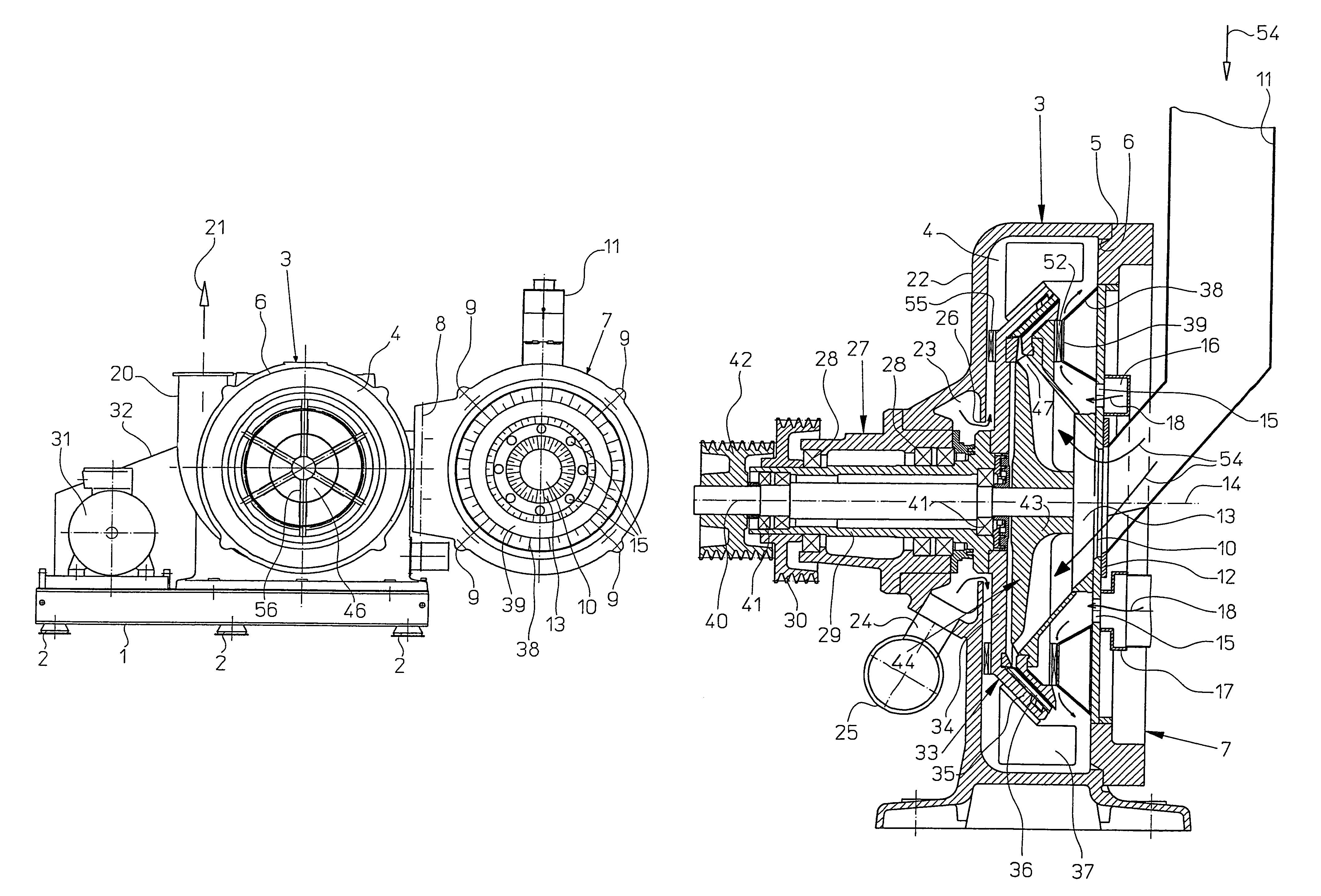
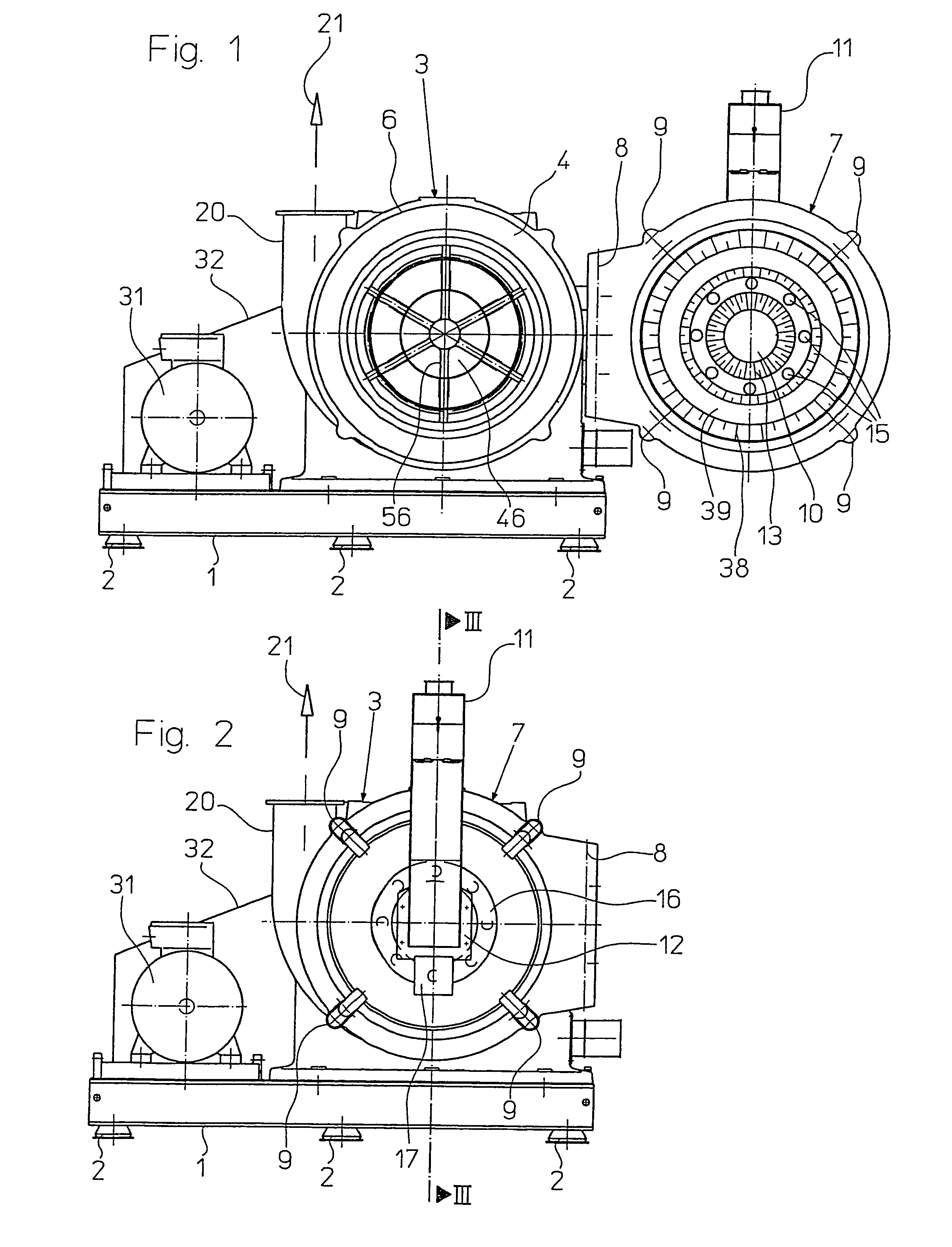
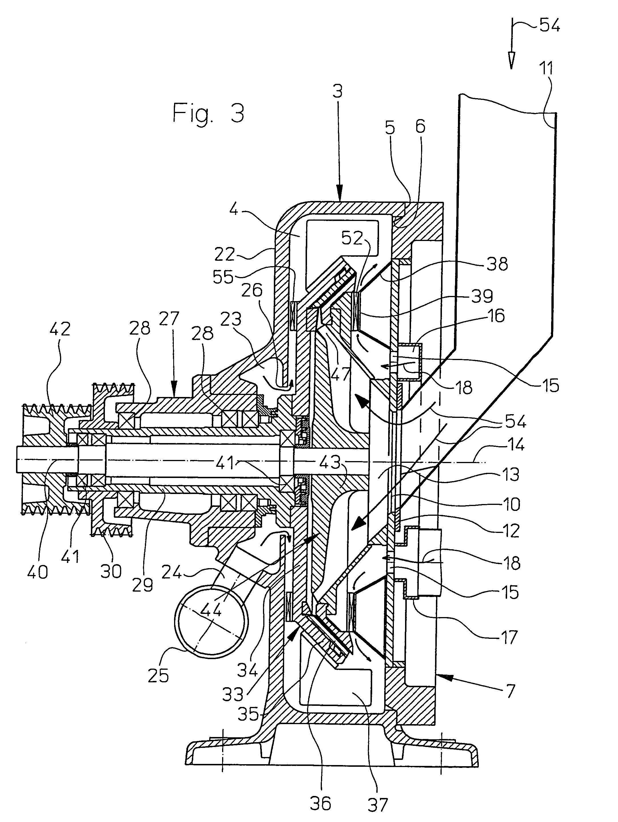
[0034]FIGS. 1 and 4 illustrate the detailed construction of an apparatus of the present invention. To begin with, FIGS. 1 and 2, which show a front view of the device with the housing door 7 open and closed, respectively, illustrate a machine substructure 1, the feet 2 of which rest on the ground / floor. The upper part of the machine substructure 1 forms a platform, on which the comminuting apparatus of the present invention is mounted.

[0035]The comminuting apparatus includes a drum-shaped housing 3 about an axis 14, and which encloses a comminuting room 4. On its front side 5, the housing 3 has a central circular opening 6, which can be closed with a housing door 7 that is pivotable around a vertical axis 8 and can be bolted shut with bolts 9.

[0036]The housing door 7 also has a central circular feeder opening 10, into which a chute 11, connected by a flange 12, terminates, the chute extending from the outside in a vertical direction, and in the bottom area in a transverse direction....


PUM


Abstract

An apparatus for comminuting material is provided. The apparatus includes two disks, which are arranged coaxially to one another inside a housing that encloses a comminuting room. The rim areas of the disks are positioned opposite one another, thus forming a milling gap, and are provided with interacting comminuting tools. To generate a mutual relative movement of the disks, at least one of the disks carries out a rotational motion around the mutual axis. To comminute the material, it is first fed into the comminuting room and subsequently radially channeled to the milling gap. For additional cooling, the disk on the intake side is arranged at an axial distance to the intake side of the housing front wall, thus forming a ringwheel-shaped cool air conduit. This can be charged with cool air, which flows through the conduit in a radial direction. In this way, the machine capacity can be increased without causing thermal damage to the material to be processed.

Description

[0001]This nonprovisional application claims priority under 35 U.S.C. § 119(a) on German Patent Application No. DE 102004050003.7, which was filed in Germany on Oct. 14, 2004, and which is herein incorporated by reference.BACKGROUND OF THE INVENTION[0002]1. Field of the Invention[0003]The present invention relates to an apparatus for comminuting material having a cool air channel.[0004]2. Description of the Background Art[0005]During the comminuting of materials in conventional devices, a considerable part of the energy required for the comminuting is converted into heat. This is caused by friction and impact forces the materials are subjected to during the comminuting process, and which primarily affect the comminuting tools.[0006]A characteristic of conventional devices during operation is air flow, which, apart from the centrifugal force, is the force that moves the materials. This so-called self-ventilation can be generated by the device itself and / or initiated from the outside....

Claims


Application Information

Patent Timeline
Patent Type & Authority Patents(United States)
IPC IPC(8): B02B1/00B02C11/08B07B4/00
CPCB02C7/06B02C7/17
Inventor PALLMANN, HARTMUT
Owner PALLMANN MASCHFAB GMBH & CO KG
Why Eureka
Try Eureka