Grinding roll

Active Publication Date: 2009-03-31
FLSMIDTH AS +1
View PDF20 Cites 25 Cited by
  • Summary
  • Abstract
  • Description
  • Claims
  • Application Information

AI Technical Summary

Benefits of technology

[0007]The wear protection elements can be fixed directly on the basic roll body for example by bonding, clamping or soldering. In a preferred embodiment, however, the wear protection elements are mounted on a retaining body which is made from a material with a

Problems solved by technology

In the case of grinding rolls which are used in particular for so-called material bed comminution the problem of high wear on the roll surface arises.
However, the previously known measures do not constitute sufficient protection for the edges of the rolls or in the case of large rolls cannot be effected or cannot be effected economically, so that it is extremely difficult to introduce

Method used


Image

  • Grinding roll
  • Grinding roll
  • Grinding roll

Examples


Embodiment Construction

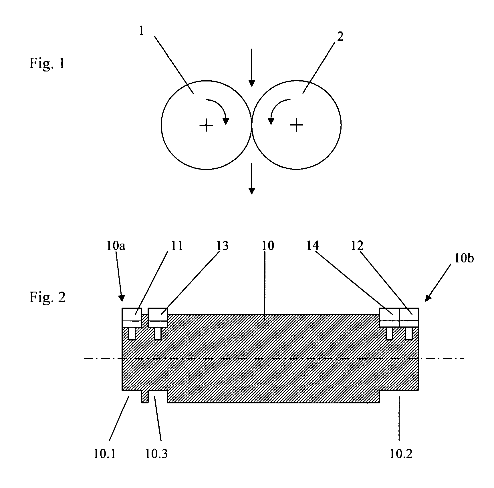
[0014]For compacting, briquetting and comminution, it is usual for two rolls 1, 2 running in opposite directions to be pressed against one another at high pressure. In so-called material bed comminution pressures of 50 MPa and above are used.

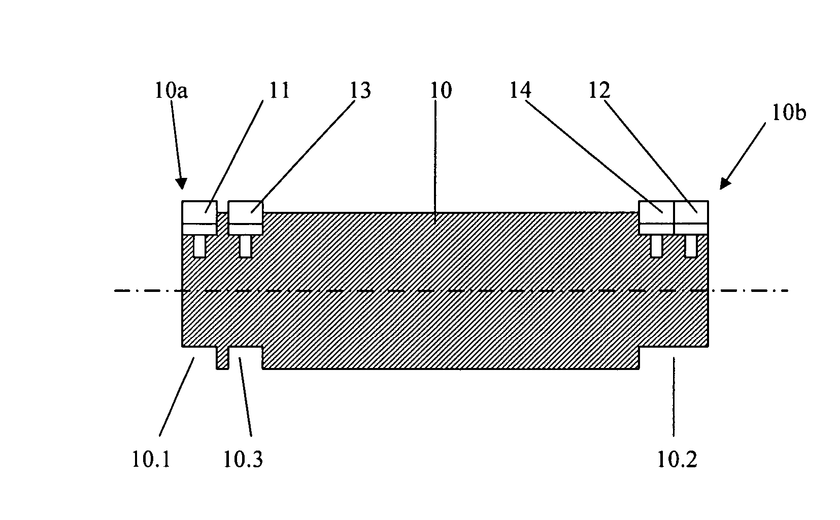
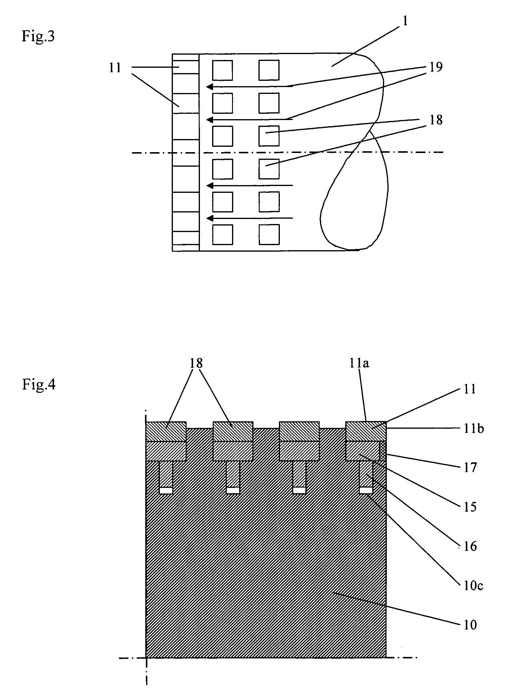
[0015]The grinding roll substantially comprises a basic roll body 10 and a plurality of wear protection elements 11, 12, 13, 14, . . . . The wear protection elements are made from hard metal and form at least a part of the roll surface. For fixing of the wear protection elements the basic roll body 10 has grooves 10.1, 10.2, 10.3 extending in the circumferential direction, a plurality of wear protection elements being disposed one behind the other in the circumferential direction in each groove.

[0016]The grooves preferably extend over the entire circumference and are provided at least in the region of the two roll ends 10a, 10b.

[0017]The wear protection elements are fixed in the circumferential grooves in such a way that there is no material of...


PUM


Abstract

The invention relates to a grinding roll with a basic roll body as well as a plurality of wear protection elements made from hard metal which form at least a part of the roll surface. The basic roll body has recesses extending in the circumferential direction, a plurality of wear protection elements being disposed one behind the other in the circumferential direction in each recess.

Description

BACKGROUND OF THE INVENTION[0001]In the case of grinding rolls which are used in particular for so-called material bed comminution the problem of high wear on the roll surface arises. It is therefore known to counteract this wear by different shaping and coating of the roll surfaces exposed to the wear. A grinding roll is known from EP-A-0 516 957 in which pin-shaped profiled bodies are disposed on the roll surface, wherein only part of each profiled body is embedded in the basic roll body whilst the remaining part projects like a spine out of the basic roll body. The individual profiled bodies are spaced so that during operation some of the material to be comminuted becomes embedded in the interstices and thereby forms an autogenous wear protection.[0002]In EP-B-0 659 108 a roller press is disclosed in which the roll surface is formed by flat zones which are made from highly wear-resistant material, the interstices between the highly wear-resistant zones being filled with a materia...

Claims


Application Information

Patent Timeline
IPC IPC(8): B02C1/10B02C13/28B02C15/16B02C17/20B02C23/00B02C7/12B02C4/30
CPCB02C4/305
Inventor BURCHARDT, EGBERTKLYMOWSKY, RENEKNECHT, JOHANNPATZELT, NORBERT
Owner FLSMIDTH AS
Why Eureka
Try Eureka