Automatic static phase error and jitter compensation in PLL circuits

a phase error and jitter compensation technology, applied in the field of phase-locked loop (pll) circuit performance enhancement, can solve the problems of increasing the difficulty of prediction and control, increasing the complexity of the circuit, and the performance of key circuit elements such as current mirrors, and affecting the performance of analog circuits, so as to achieve automatic optimization of the jitter performance of the pll

Inactive Publication Date: 2009-03-31
GLOBALFOUNDRIES INC
View PDF3 Cites 35 Cited by
  • Summary
  • Abstract
  • Description
  • Claims
  • Application Information

AI Technical Summary

Benefits of technology

[0010]In accordance with the present embodiments, the creation of new feedback loops for the optimization of phase-locked loops (PLL) static phase error and jitter performance is provided. Thus, the present system first enables the realization of an efficient way to automatically adjust the static phase error of a PLL, either to a minimum value or to a specific target mean value. This can be used during PLL operation, enabling the minimum or target phase error value to be dynamically maintained. In another aspect, the present system enables the realization of an efficient way to automatically optimize the jitter performance of a PLL.

Problems solved by technology

As integrated circuit technology advances, it becomes more and more difficult to predict and to control, within tight tolerances, the behavior of integrated circuit elements.
In addition, non-idealities in the performance of key circuit elements such as current mirrors also tend become more and more pronounced with each ensuing technology generation.
The problems associated with advancing integrated circuit technology strongly affect analog circuits, and particularly phase-locked loop (PLL) circuits.
Such approaches do not treat static phase error directly as a quantity to be measured and then compensated.
Furthermore, these techniques do not allow for the achievement of a target non-minimum static phase error.
Similarly, approaches to jitter minimization have focused on open-loop techniques that improve the underlying baseline jitter behavior of the overall PLL, Such approaches do not enable optimization of the PLL as a function of the noise content of the input reference signal, for example.

Method used


Image

  • Automatic static phase error and jitter compensation in PLL circuits
  • Automatic static phase error and jitter compensation in PLL circuits
  • Automatic static phase error and jitter compensation in PLL circuits

Examples


Embodiment Construction

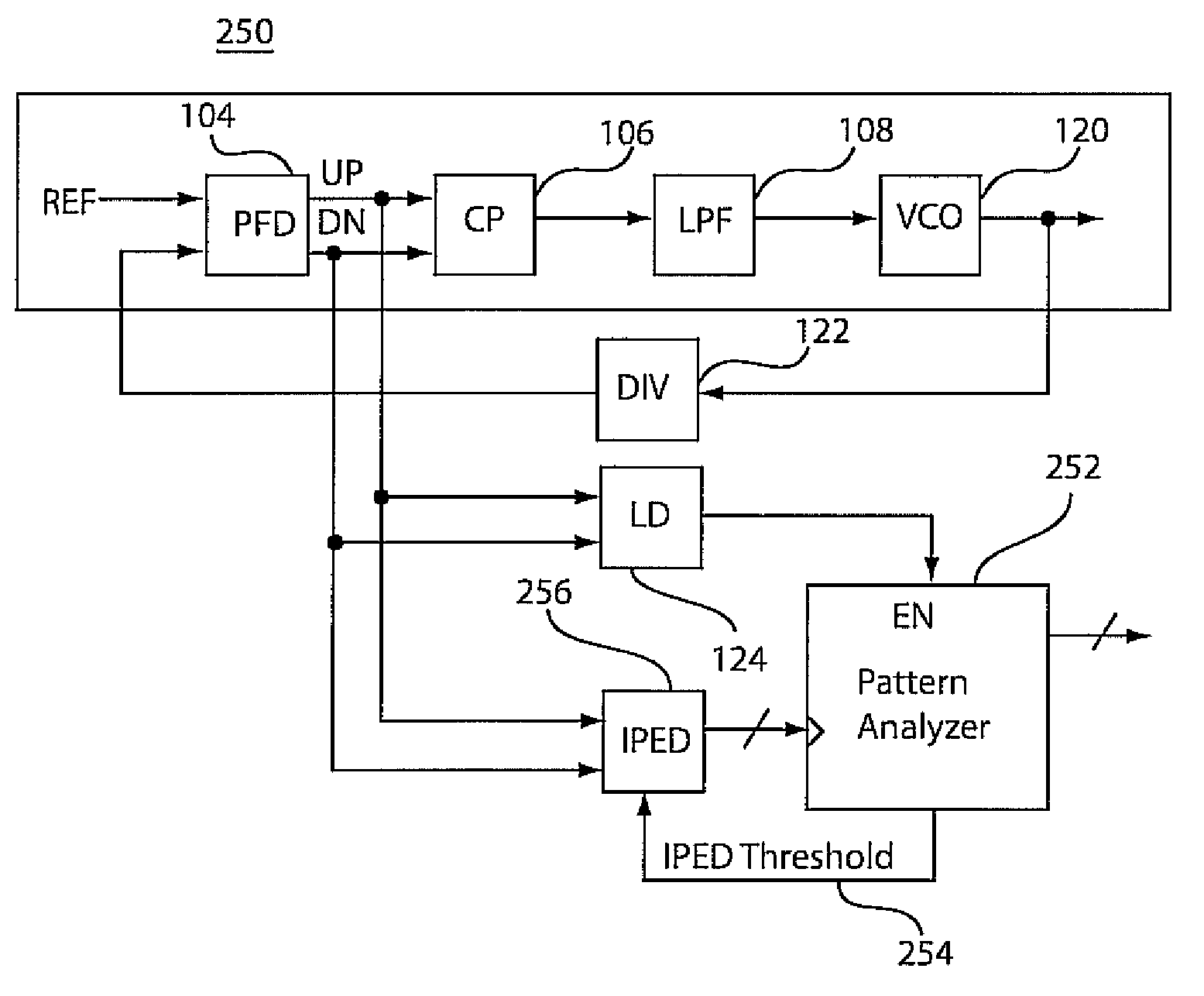
[0027]Embodiments in accordance with the present principles address the following issues. An efficient way to automatically adjust static phase error of a phase locked loop (PLL) is addressed. Typically, it is desirable for PLL static phase error to be as close to zero as possible. In accordance with one feature, automatic realization of a minimum mean static phase error is provided, or, alternately, the realization of a given fixed target value of static phase error. In both cases, the static phase error is dynamically maintained during PLL operation.

[0028]A second issue that is addressed includes the development of an efficient way to automatically optimize the jitter performance of a PLL. In general, overall PLL jitter performance is dependent on both internally generated jitter (such as from a voltage controlled oscillator (VCO)) as well as unknown external sources of jitter (such as from a reference clock). One way to optimize PLL jitter performance is to dynamically adjust PLL...


PUM


Abstract

An instantaneous phase error detector (IPED) and method includes a first gate configured to logically OR output phase error signals as data to a first latch, and a second gate configured to logically combine the output phase error signals to clock the first latch. A delay element delays to the data to the first latch where the output of the first latch provides instantaneous phase error change information. A second latch is coupled to the output phase error signals to output a lead / lag signal to indicate which of the output phase error signals is leading. A phase-locked loop employing the output of the IPED is also disclosed along with static phase measurement and jitter optimization features.

Description

BACKGROUND[0001]1. Technical Field[0002]The present invention generally relates to performance enhancement in phase-locked loop (PLL) circuits, and more particularly to automatic static phase error and jitter compensation in PLL circuits.[0003]2. Description of the Related Art[0004]As integrated circuit technology advances, it becomes more and more difficult to predict and to control, within tight tolerances, the behavior of integrated circuit elements. These integrated circuit elements may include transistors as well as passive elements such as resistors and capacitors. In addition, non-idealities in the performance of key circuit elements such as current mirrors also tend become more and more pronounced with each ensuing technology generation.[0005]As the variability in individual devices grows and as device performance departs further and further from the ideal, it becomes increasingly important to identify efficient ways to compensate for process, voltage, temperature, and aging...

Claims


Application Information

Patent Timeline
Patent Type & Authority Patents(United States)
IPC IPC(8): H03L7/06
CPCH03D13/004H03L7/087H03L7/0896H03L7/0898H03L7/095
Inventor FRIEDMAN, DANIEL J.LIU, YONGRHEE, WOOGEUN
Owner GLOBALFOUNDRIES INC
Why Eureka
Try Eureka