Work support and management system for working machine

a management system and working machine technology, applied in the direction of thinning machines, program control, instruments, etc., can solve the problems of difficult to employ a system prepared for a particular type of working machine in another type of working machine, and a great deal of time is required to prepare the system for adaptation

Inactive Publication Date: 2009-04-07
NIHON KENKI CO LTD
View PDF53 Cites 27 Cited by
  • Summary
  • Abstract
  • Description
  • Claims
  • Application Information

AI Technical Summary

Benefits of technology

[0011]It is an object of the present invention is to provide a work support and management system for a working machine, which can easily be employed in different types of working machines in common, and which can inexpensively be prepared with ease.
[0031]With that feature, the total amount of completed work after the completion of total work can be confirmed, and the management efficiency can be increased.

Problems solved by technology

However, when the desired site landform (target landform) and the actual site landform (current site landform) are displayed in superimposed relation, or when the difference between the desired site landform and the actual site landform is graphically displayed in a plan view, it is difficult to employ a system prepared for a particular type of working machine in another type of working machine because different types of working machines carry out different kinds of work.
Accordingly, a new system must be prepared for each type of working machine, and a great deal of time is required to prepare the systems adapted for the various types of working machines.

Method used


Image

  • Work support and management system for working machine
  • Work support and management system for working machine
  • Work support and management system for working machine

Examples


first embodiment

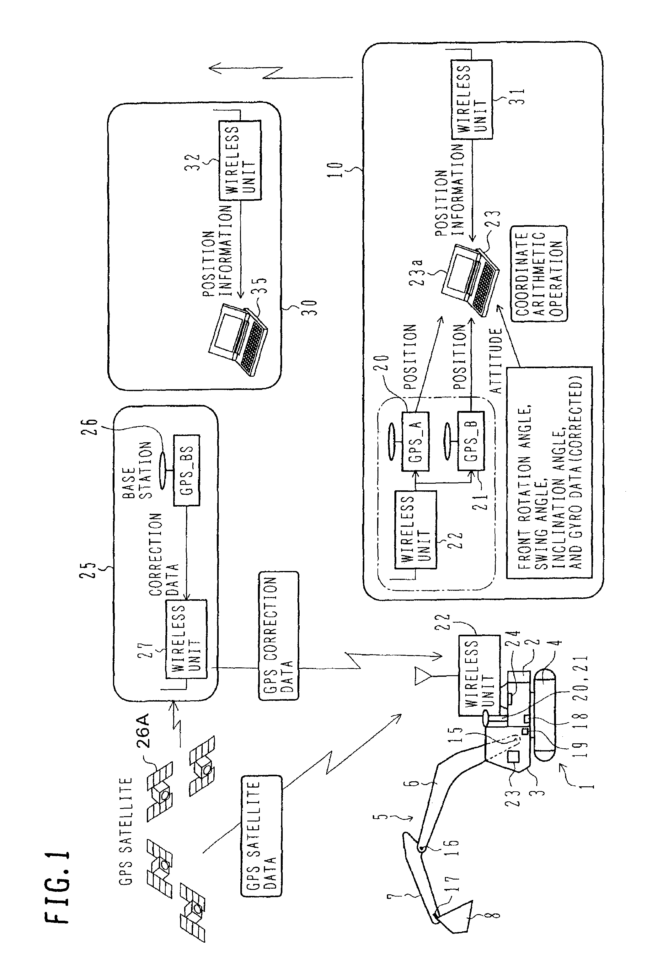
[0053]FIG. 1 is an illustration showing the overall configuration of a work support and management system in which the present invention is applied to a crawler mounted hydraulic excavator.

[0054]Referring to FIG. 1, a hydraulic excavator 1 comprises a swing body 2, a cab 3, a travel body 4, and a front operating mechanism 5. The swing body 2 is rotatably mounted on the travel body 4, and the cab 3 is located in a front left portion of the swing body 2. The travel body 4 is illustrated as being of the crawler type, but it may be of the wheel type having wheels for traveling.

[0055]The front operating mechanism 5 comprises a boom 6, an arm 7, and a bucket 8. The boom 6 is mounted to a front central portion of the swing body 2 rotatably in the vertical direction. The arm 7 is mounted to a fore end of the boom 6 rotatably in the back-and-forth direction, and the bucket 8 is mounted to a fore end of the arm 7 rotatably in the back-and-forth direction. The boom 6, the arm 7, and the bucke...

second embodiment

[0095]the present invention will be described with reference to FIG. 9 through 12.

[0096]FIG. 9 is an illustration showing the overall configuration of a work support and management system according to the second embodiment when the present invention is applied to a mine sweeping machine.

[0097]Referring to FIG. 9, a mine sweeping machine 101 is constructed by using a crawler mounted hydraulic excavator as a base machine, and has the same basic structure as the hydraulic excavator shown in FIG. 1. Similar components to those in FIG. 1 are denoted by respective numerals increased by 100. However, a front operating mechanism 105 includes a rotary cutter 108 instead of the bucket, and a radar explosive probing sensor 181 is mounted to a lateral surface of an arm 107. The sensor 181 is movable along the lateral surface of an arm 107 through a telescopic extendable arm 182. Also, the sensor 181 is rotatable relative to the telescopic extendable arm 182 by a probing sensor cylinder.

[0098]An...

third embodiment

[0124]the present invention will be described with reference to FIG. 13 through 16.

[0125]FIG. 13 is an illustration showing the overall configuration of a work support and management system according to the third embodiment in which the present invention is applied to a ground improving machine.

[0126]Referring to FIG. 13, a ground improving machine 201 is constructed by using a crawler mounted hydraulic excavator as a base machine, and has the same basic structure as the hydraulic excavator shown in FIG. 1. Similar components to those in FIG. 1 are denoted by respective numerals increased by 200. However, a front operating mechanism 205 includes, instead of the bucket, a stirrer 208 for spraying a solidifier into soft ground and stirring it.

[0127]An on-board system 210 is mounted on the ground improving machine 201, and a GPS base station 225 and a management room 230 are installed in other places. The GPS base station 225 and the management room 230 also have the same basic configu...


PUM


Abstract

An excavation support database 40 includes a display table 47 and a display specifics table 48, which serve as storage means dedicated for display. The state of a working region per mesh is stored in the display table 47, and a discriminative display method (display color) is stored in the display specifics table 48 corresponding to the state per mesh. Reference is made to the display specifics table 48 on the basis of the state (height) per mesh, which is stored in the display table 47, to read the corresponding display color from the display specifics table 48, thereby displaying the state of the working region in a color-coded manner. Operation support and management realized with this system can easily be employed in different types of working machines in common and can inexpensively be performed with ease.

Description

TECHNICAL FIELD[0001]The present invention relates to a work support and management system for a working machine, which measures and displays the three-dimensional position and state of each of working machines used for modifying topographic and geological features or improving ground and underground conditions, such as a hydraulic excavator, a mine sweeping machine and a ground improving machine, thereby supporting and managing work carried out by the working machine.BACKGROUND ART[0002]Aiming at an improvement of working efficiency, some of working machines, such as hydraulic excavators, are equipped with work supporting devices in a cab or an operating room for remote control. In particular, due to facilitation in three-dimensional position measurement using the GPS, it has recently been proposed to measure the three-dimensional position of a working machine and to display the measured position together with, e.g., a target position of work.[0003]One example of such a support dev...

Claims


Application Information

Patent Timeline
Patent Type & Authority Patents(United States)
IPC IPC(8): E02F5/02G05D1/02E02F9/20E02F9/26G06T17/05
CPCE02F9/2025G07C3/08E02F9/26
Inventor OGURA, HIROSHIISHIBASHI, HIDETOHATORI, KEIJIWATANABE, HIROSHI
Owner NIHON KENKI CO LTD
Why Eureka
Try Eureka