
Railway truck pedestal bearing adapter

a technology for rail freight cars and adapters, which is applied in the direction of axle boxes, axle boxes, rail components, etc., can solve the problems of poor performance of railway freight car trucks, the tendency of the adapter pads to move longitudinally,

Active Publication Date: 2009-04-07
AMSTED RAIL CO INC
View PDF4 Cites 34 Cited by
  • Summary
  • Abstract
  • Description
  • Claims
  • Application Information

AI Technical Summary

Benefits of technology

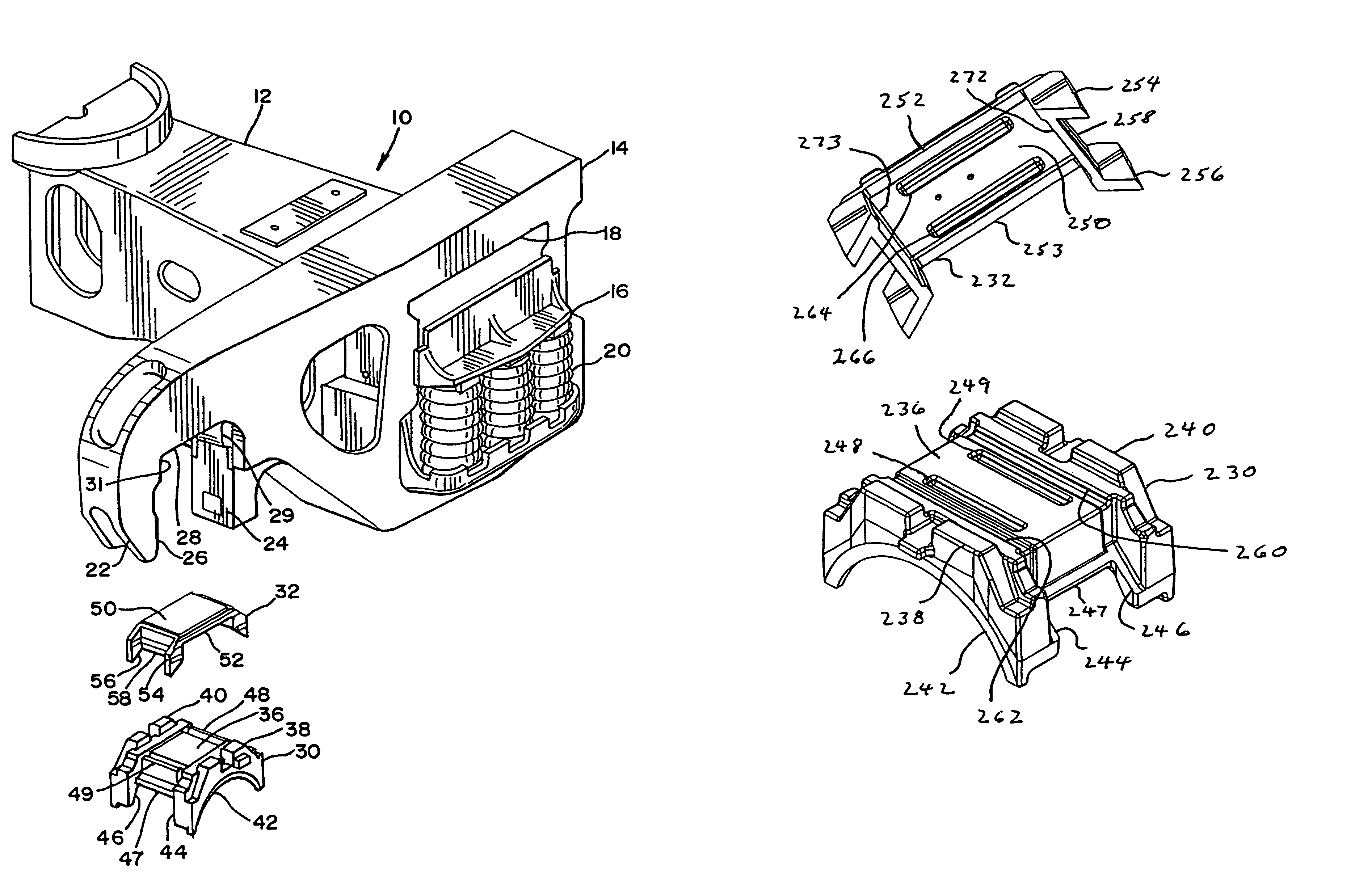
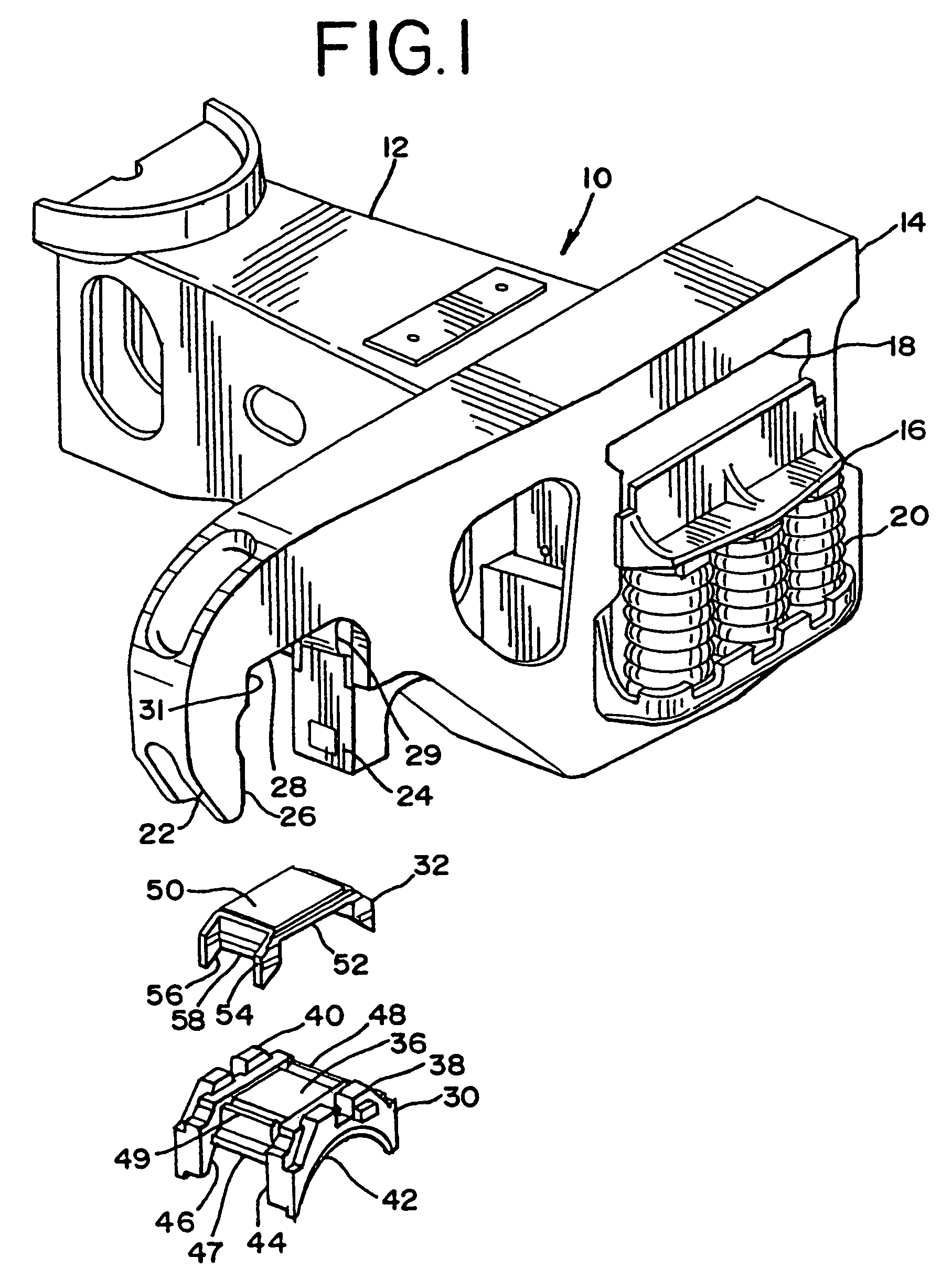
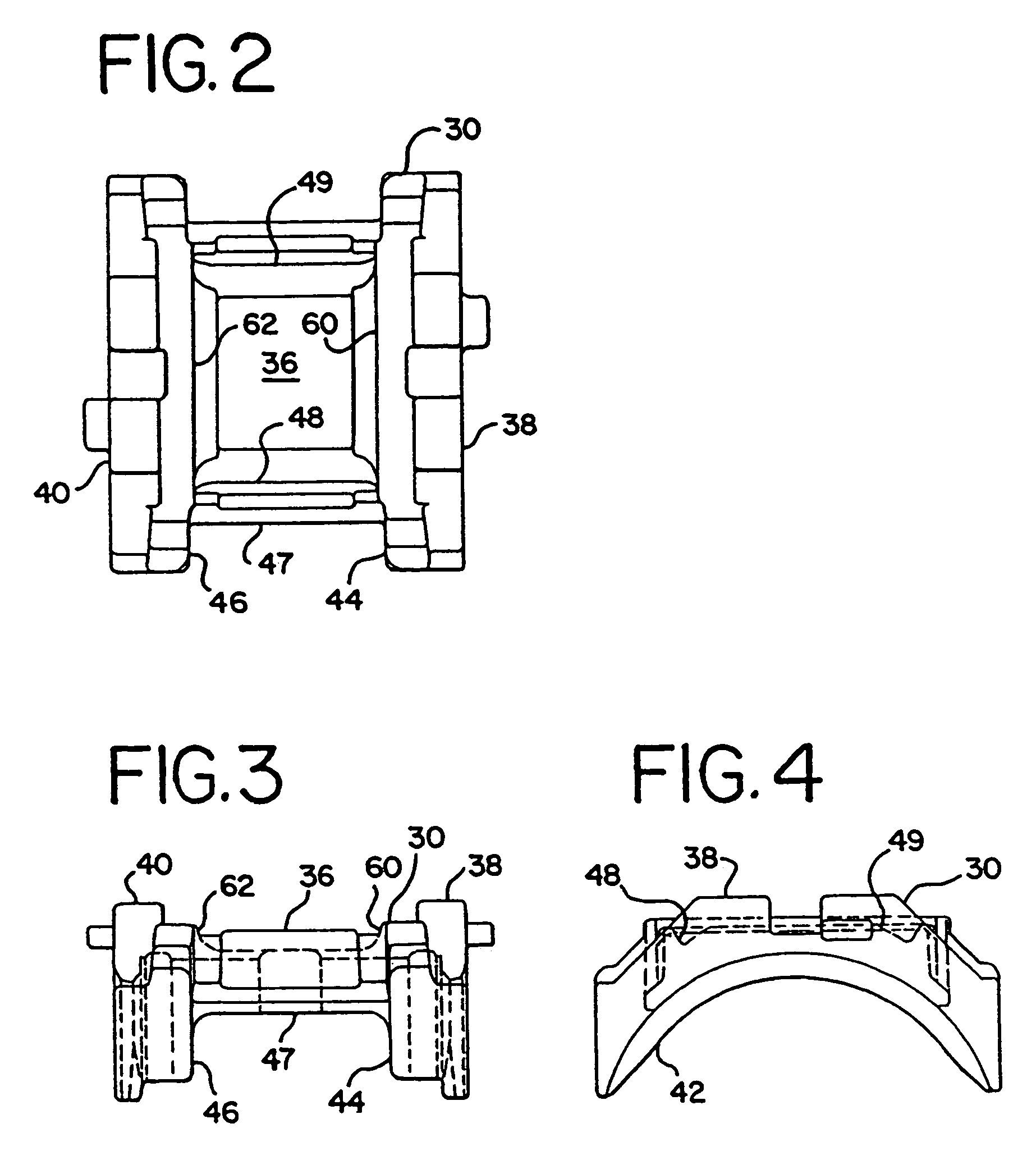
[0006]The wheel axle assemblies themselves are received in openings, commonly referred to as pedestal jaw openings, at longitudinal ends of each sideframe. The wheel axle assemblies themselves extend laterally between the sideframes, and hence, also laterally between the two spaced railway tracks. For improved performance of the railway freight car truck, it is desirable to receive the bearings press fit on each axle end into a bearing adapter assembly. The improved bearing adapter assembly of the present invention is comprised of a cast steel, unitary bearing adapter. This bearing adapter includes lateral edges themselves having arcuate cutouts to be placed over the bearing assembly. The bearing adapter further comprises depending shoulders that extend from each longitudinal edge of the bearing adapter. The shoulders at each longitudinal edge of the bearing adapter themselves are laterally spaced to form an opening there between. Further, the bearing adapter includes depressions that extend laterally and are spaced longitudinally across the top section of the bearing adapter. It should be understood that the top section of such bearing adapter is generally rectangular in structure, such that the depressions are near each longitudinal edge of the bearing adapter. These depressions can be of a general v-shape, formed by acute angle cuts into the top section of the bearing adapter, or they could be of an arcuate nature as well.
[0008]The bearing adapter of the present invention has the legs extending around the thrust lugs. In addition to this the new design pad has the additional interlock on the bottom side of the adapter pad, which allows the pad to function in shear. With the proper relationship between cross section and hardness of the pad, a spring rate is designed into the elastomer material of the pad. The elastomer then allows the railway truck wheel-sets to move from a high warp stiffness position to that of radial steering position when the truck passes through curves. Once through the curve the elastomer acts as a spring to re-center the adapter to a neutral position.

Problems solved by technology

One problem with this assembly is the tendency of the adapter pad to move longitudinally across the top of the bearing adapter.
This is an undesirable situation leading to poor performance of the railway freight car truck.

Method used


Image

  • Railway truck pedestal bearing adapter
  • Railway truck pedestal bearing adapter
  • Railway truck pedestal bearing adapter

Examples


Embodiment Construction

[0025]Referring now to FIG. 1 of the drawings, the lateral end of each sideframe 14 is seen to be comprised of a downwardly extending pedestal jaw 22. The inside wall 26 of pedestal jaw 22, along with roof section 28 and vertical face 24 are seen to combine to form the pedestal jaw opening. At the interface between vertical face 24 and roof section 28, there is seen to be an inner thrust lug 29. Inner thrust lug 29 is seen to comprise an angled section that extends from an upper section of vertical face 24 to an inward section of roof section 28. Similarly, but not entirely seen in this perspective view of FIG. 1, outer thrust lug 31 is seen to comprise an angled section extending from an upper portion of inside wall 26 extending to an inner portion of roof section 28.

[0026]Another part of the present invention includes bearing adapter 30, which is seen to be a generally rectangular structure having depending legs extending therefrom. Bearing adapter 30 is usually comprised of a uni...


PUM


Abstract

A railway car truck is provided that includes two sideframes and a bolster. Each sideframe has a pedestal opening at each end to receive a bearing adapter assembly. The bearing adapter assembly includes a cast steel bearing adapter that is formed to fit on top of a bearing assembly. An adapter pad, comprised of a selected hardness elastomer, is fit on top of the bearing adapter. Protrusions extend from the adapter pad and are received in depressions in the bearing adapter to provide longitudinal stability for the adapter pad on the bearing adapter itself. Each adapter pad includes at least two wear tabs extending laterally outwardly from a top section of the adapter pad.

Description

[0001]This application is a continuation in part to U.S. patent application Ser. No. 10 / 863,712, filed Jun. 8, 2004, now U.S. Pat. No. 7,308,855 which application is incorporated by reference. The present invention relates to a railway freight car truck and, more particularly, to a pedestal bearing adapter having a wear indicator for use in the pedestal jaw opening of the sideframe of a railway freight car truckBACKGROUND OF THE INVENTION[0002]In a railway freight car truck, two axles are held in a pair of laterally spaced sideframes, with a bolster extending laterally between and supported on each sideframe. The wheels are press fit on the axles, with the ends of the axles also fitted with a roller bearing assembly. The roller bearing assembly itself is fit into a bearing adapter that is fit into a pedestal jaw opening at the longitudinal end of each sideframe. The ends of the bolsters are themselves supported on spring groups, which are supported on the lower portion of the center...

Claims


Application Information

Patent Timeline
Patent Type & Authority Patents(United States)
IPC IPC(8): B61F5/26B61F3/00B61F5/30B61F5/32
CPCB61F5/305B61F5/32
Inventor VAN AUKEN, CHARLES L.
Owner AMSTED RAIL CO INC
Learn More