Molten metal level burner output control for aluminum melt furnace

a technology of aluminum melt furnace and burner, which is applied in the direction of furnaces, heat treatment equipment, lighting and heating equipment, etc., can solve the problems of manual operation, inconvenient maintenance, and difficulty in adjusting the link rod type assembly,

Active Publication Date: 2009-04-07
HONDA MOTOR CO LTD
View PDF15 Cites 7 Cited by
  • Summary
  • Abstract
  • Description
  • Claims
  • Application Information

AI Technical Summary

Benefits of technology

[0021]The present invention is directed toward a method and control system for a metal melting furnace that provides improved control over operation of the melting burners and holding burners.

Problems solved by technology

Such a problem could be a blockage of charging material, preventing the charging material from reaching the melting burners 20, or simply that the charging tower 10 is empty.
Unfortunately, repeated cycling or rising / falling of the metal level in the bath between the high level and the low level erodes the refractory lining (RL) of the metal holding area 14 and, over time, requires rebuilding of the metal holding area lining.
Naturally, rebuilding the refractory lining (RL) is expensive and requires the metal melting furnace to be taken off-line for an extended period of time.
Unfortunately, adjusting the link-rod type assembly is a manual operation that is imprecise and problematic.
Improper adjustment of the link rod assembly causes the high and low setpoints or limits to deviate from the actual high and low opening positions of the air valve 32, and may result in undue cycling of the metal temperature between the high and low limits.

Method used


Image

  • Molten metal level burner output control for aluminum melt furnace
  • Molten metal level burner output control for aluminum melt furnace
  • Molten metal level burner output control for aluminum melt furnace

Examples


first embodiment

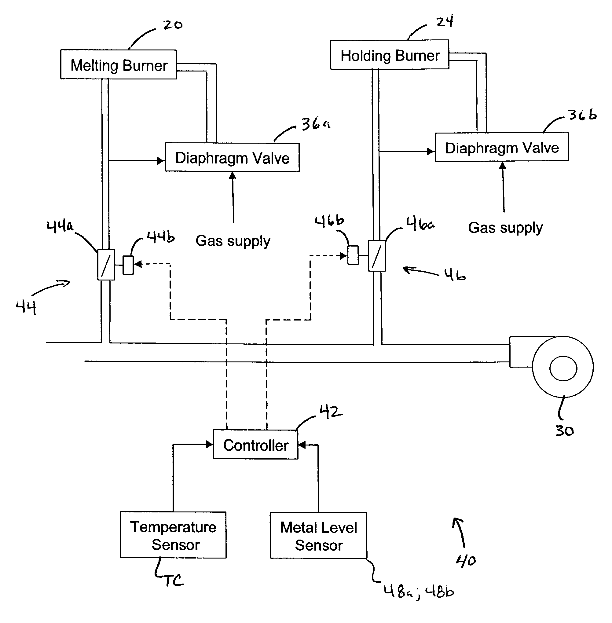
[0037]Two different methods and arrangements 48a, 48b for measuring metal heights are described hereinafter. In accordance with a first embodiment, while the metal temperature is sensed and controlled as described hereinbefore, molten metal level is sensed by a first arrangement comprising a series of level sensing probes. For example, the level sensing probes described hereinbefore could be used. According to this embodiment, when a low metal level is sensed by the low probe (L), the controller 42 actuates the melting burner air valve servo-motors 44b to move the melting burner air valves 44a into a high or full-open setting, and the melting burners 20 are operated full-on. However, when a high metal level is not sensed by the high probe (H) (i.e., metal level between high and low levels), the controller 42 actuates the melting burner air valve servo-motors 44b to move the melting burner air valves 44a into a mid-range position, which is between the full-open and the low setting), ...

second embodiment

[0042]With reference to FIG. 6, in a second embodiment, and with the metal temperature sensed and controlled as discussed previously, the molten metal level sensing arrangement 38b includes laser sensor 50, which is able to measure metal heights at a sensitivity of at least tenths, and preferably hundredths, of an inch. In this arrangement 38b, none of the metal level sensing probes, except the high-high level sensing probe (HH) and the ground probe (G), remain in the control system 40. The high-high level probe (HH) is retained and serves to notify the controller 42 that the metal bath is overfull, as may be necessary should the laser sensor 50 fail. Thus, the high-high level probe (HH) serves as a backup to prevent overfilling of the metal bath, which in an extreme case would cause molten metal to overflow the bath and spill out around the furnace.

[0043]By sensing molten metal level with the laser sensor 50, the controller is provided with highly accurate information on the metal ...


PUM

PropertyMeasurementUnit
temperatureaaaaaaaaaa

Abstract

A control system and method for controlling a temperature and molten metal height in a gas-fired metal melting furnace whereby metal height and temperature may be more reliably maintained. The control system includes a controller that receives information on metal temperature and metal height. The controller controls metal melting burners so as to operate at different settings between a high output and a low output based upon sensed metal height.

Description

BACKGROUND OF THE INVENTION[0001]1. Field of the Invention[0002]The present invention generally relates to metal melting furnaces and, more particularly, toward a method and system for controlling a metal melting furnace based upon sensed molten metal heights and temperatures to permit more efficient operation of the furnace.[0003]2. Description of Related Art[0004]Gas fired metal melting furnaces are well known in the art. One such type of furnace, illustrated in FIG. 1, includes a charging tower 10, a melting area 12, a molten metal holding area 14, and a launder 16 that leads to a ladle or dispensing area 18.[0005]The charging tower 10 is vertically above the melting area 12, and includes a removable cover such that new charging material (i.e., ingots and scrap) to be melted can be introduced into the charging tower 10. Since the charging material is disposed in the tower 10 and vertically above the melting area 12, the charging material is pre-heated prior to reaching the meltin...

Claims


Application Information

Patent Timeline
Patent Type & Authority Patents(United States)
IPC IPC(8): C21B13/00C21B7/24
CPCF27D21/0014F27D21/0028C21C5/567C21C2005/5288Y10S266/90Y02P10/20
Inventor SCHROEDER, KARLRETHMAN, DON
Owner HONDA MOTOR CO LTD
Why Eureka
Try Eureka