Electric power generation using power turbine aft of LPT

a gas turbine and power generation technology, applied in the direction of electric generator control, machine/engine, magnetic circuit characterised by magnetic materials, etc., can solve the problems of reducing the ability to operate the engine properly, reducing the operability of the engine, and not directly addressing the problem of producing supplemental electrical power, etc., to achieve controllable power extraction, reduce the required size of the generator, and increase the power extraction

Inactive Publication Date: 2009-04-07
GENERAL ELECTRIC CO
View PDF27 Cites 83 Cited by
  • Summary
  • Abstract
  • Description
  • Claims
  • Application Information

AI Technical Summary

Benefits of technology

[0014]Another advantage of the present invention is controllable power extraction from the turbofan engines.
[0015]Yet another advantage of the present invention is the production of energy at idle from the exhaust of the low-pressure turbine.
[0016]Another advantage of the present invention is that when extra power generation is not desired, thrust path of the engine is not obstructed.
[0017]Another advantage of the present invention is that the speed of the aft mounted turbine is independent of the other engine spools and does not mechanically impact engine performance or operability, the turbine can be driven at high speeds, thereby reducing the required size of the generator.
[0018]Another advantage of the present invention is the use of an inside-out generator that enables the use of electromagnetic machine types suitable for the harsh environment of the aft section of the engine.
[0019]Yet another advantage of the present invention is that the placement of the generator aft of the turbine engine enables injection of power into the accessory gearbox.

Problems solved by technology

When operating an aircraft engine at relatively low power levels, e.g., while idly descending from altitude, extracting additional electrical power from the engine mechanical power may reduce the ability to operate the engine properly.
Extracting this additional mechanical power from an engine when it is operating at relatively low power levels (e.g., at or near idle descending from altitude, low power for taxi, etc.) may lead to reduced engine operability.
The LP engine spool provides an alternate source of power transfer, however, the relatively lower speed of the low-pressure (LP) engine spool typically requires the use of a gearbox, as slow-speed electrical generators are often larger than similarly rated electrical generators operating at higher speeds.
While this approach can provide power sufficient to operate the aircraft system, it does not directly address the problems associated with producing supplemental electrical power while the engine is running at lower speeds or at idle.
However, this system has not been widely used in practical applications.
However, the hot gasses exhausted from the LP turbine are corrosive and create damaging conditions for typical electric generators.

Method used


Image

  • Electric power generation using power turbine aft of LPT
  • Electric power generation using power turbine aft of LPT
  • Electric power generation using power turbine aft of LPT

Examples


Embodiment Construction

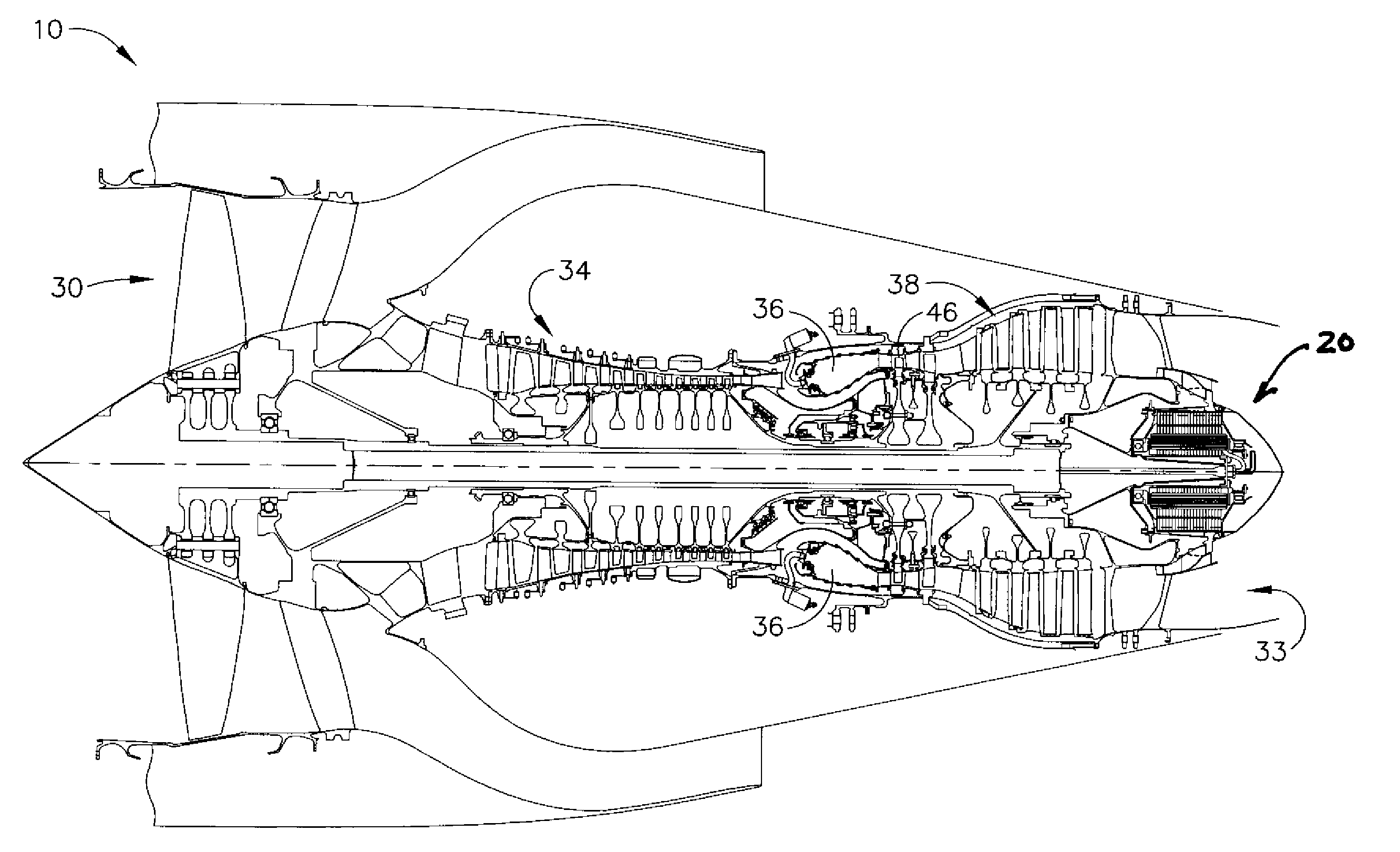
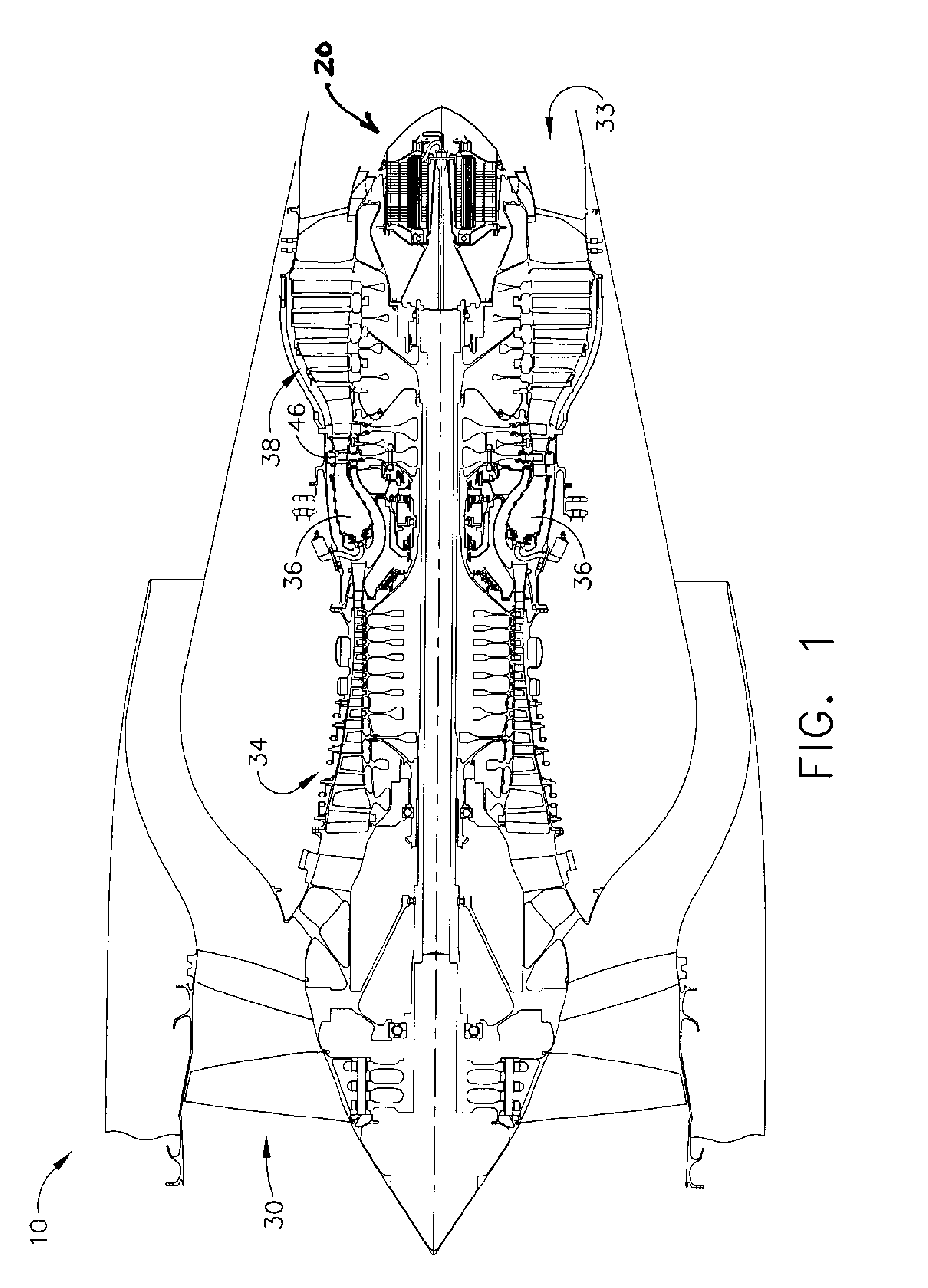
[0038]A typical gas turbine engine 10 consists of four basic elements shown in FIG. 1, the compressor 34 which increases the pressure and temperature of the air that enters an inlet 30, a combustion chamber 36 that raises the temperature and pressure of the air further, a high pressure and low pressure turbine 38, 46 that converts the temperature rise into rotational energy, and an exhaust nozzle 33 which accelerates the air using the remainder of the energy added in the combustor 36, which produces a high velocity jet exhaust that propels an aircraft through the air at high speeds.

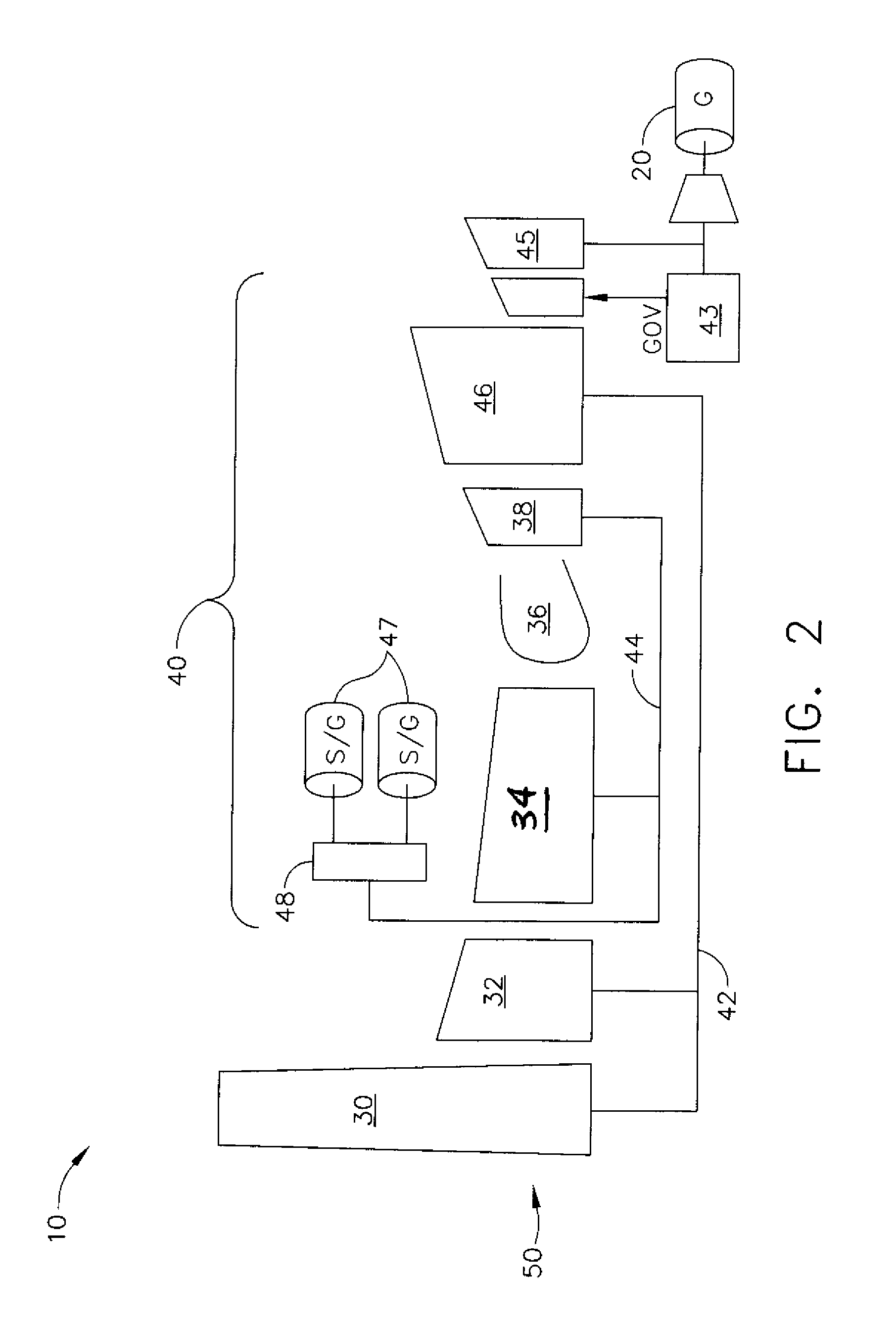
[0039]FIG. 2 illustrates a component model of a gas turbine engine 10 where the inside out generator 20 is placed aft of the low-pressure turbine 46. The engine 10 has a serial axial flow relationship between the components, which include a high-pressure compressor 34, a combustor or burner 36, and a high-pressure turbine 38. These components make up the core engine 40, and are downstream from an inlet fa...


PUM


Abstract

An inside out generator disposed aft of the low-pressure turbine spool to generate power for the electrical demands of an aircraft system. The low-pressure turbine discharge flow is used to drive the power turbine, which is coupled to the generator. The generator is able to extract power at idle conditions of the aircraft engine from ducting the discharge through the inside out generator. The system eliminates the placement of a generator in the hot gas path of the discharge, and enables the injection of power directly to the accessory gear box of the engine.

Description

FIELD OF THE INVENTION[0001]The present invention relates to electrical machines, and more particularly to the production of electrical power from gas turbine engines.BACKGROUND OF THE INVENTION[0002]A gas turbine engine generally includes one or more compressors followed in turn by a combustor and high and low pressure turbines. These engine components are arranged in serial flow communication and disposed about a longitudinal axis centerline of the engine within an annular outer casing. The compressors are driven by the respective turbines and compressor air during operation. The compressor air is mixed with fuel and ignited in the combustor for generating hot combustion gases. The combustion gases flow through the high and low pressure turbines, which extract the energy generated by the hot combustion gases for driving the compressors, and for producing auxiliary output power.[0003]The engine power is transferred either as shaft power or thrust for powering an aircraft in flight....

Claims


Application Information

Patent Timeline
Patent Type & Authority Patents(United States)
IPC IPC(8): F02C1/06
CPCF01D15/10F02C7/32F02K3/06H02K7/1823H02K19/20H02K1/02Y02T50/672Y02T50/60
Inventor KERN, JOHN M.CHUNG, KIYOUNGQU, RONGHAIWU, WEIYOUNG, CRAIG D.TOOT, PETER D.GLYNN, CHRISTOPHERCOMPTON, TOM
Owner GENERAL ELECTRIC CO
Why Eureka
Try Eureka