Integrated searchlight lighthead

a searchlight and lighthead technology, applied in the field of integrated searchlight lightheads, can solve the problems of increasing maintenance costs and time, preventing degradation of ir light sources, and heat generated by visible light sources not being sufficiently dissipated, so as to improve illumination performance, reduce conductive heat transfer, and increase reflector area

Active Publication Date: 2009-04-14
HONEYWELL INT INC
View PDF9 Cites 9 Cited by
  • Summary
  • Abstract
  • Description
  • Claims
  • Application Information

AI Technical Summary

Benefits of technology

[0004]The two illumination sources are separated with insulation material and an air gap to improve illumination performance and meet severe operating conditions. The separation provides cooling from convective heat transfer and greatly reduces conductive heat transfer from the high power visible lighting portion of the canopy to the IR illumination portion of the canopy. The IR portion of the canopy is isolated to protect the IR sources from high temperatures.
[0005]The reflective device for visible illumination is integrated into the housing to increase reflector area and reduce maintenance costs and time. The increase in reflector area has a direct positive effect on visible light intensity. Embodiments may include U.S. Pat. No. 6,960,776 to Machi titled “IR Diode Based High Intensity Light,” herein incorporated by reference, which describes a high intensity, low power infrared light assembly for use on aircraft or other vehicles for landing, taxi mode, or search operations. These features contribute to reducing the size of the envelope required to harness the IR illumination sources, reducing the amount of heat generated by the searchlight, and allows the visible portion of the canopy to be larger, increasing reflector area and thus visible light intensity.

Problems solved by technology

Both light sources, however, are within the same lamp head (and the same lamp face), so that heat generated from the visible light source is not dissipated sufficiently to prevent degradation of the IR light source due to high temperatures generated by the heat from the visible light source.
The design includes a separate reflector which must be attached to the housing, and which increases maintenance costs and time.

Method used


Image

  • Integrated searchlight lighthead
  • Integrated searchlight lighthead
  • Integrated searchlight lighthead

Examples


Embodiment Construction

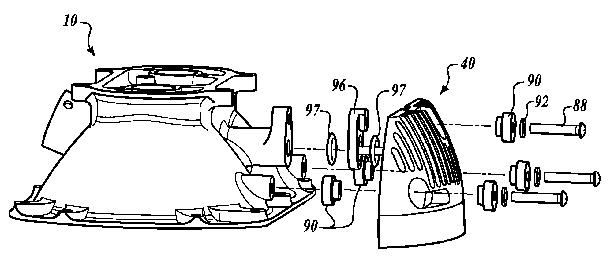
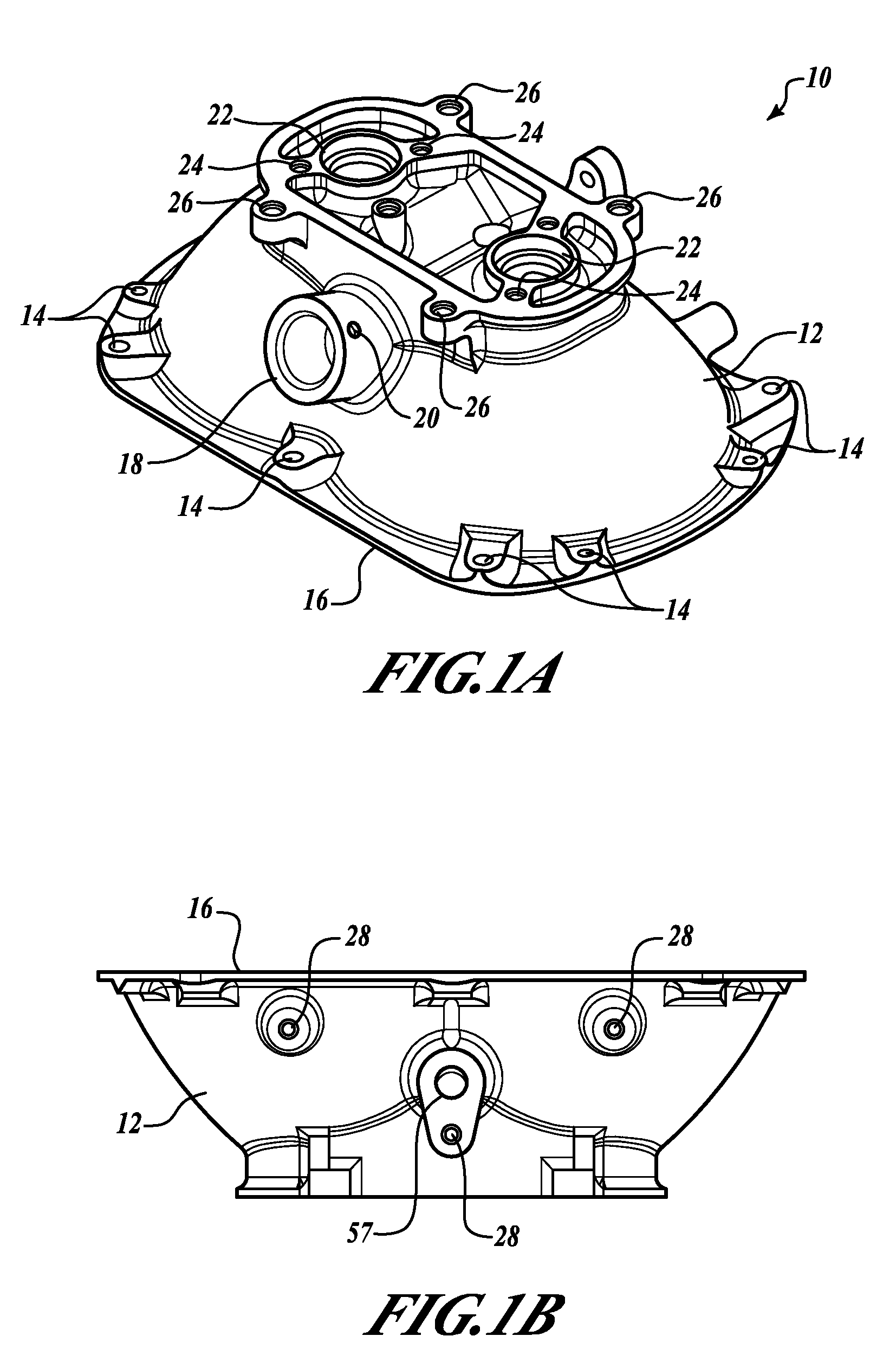
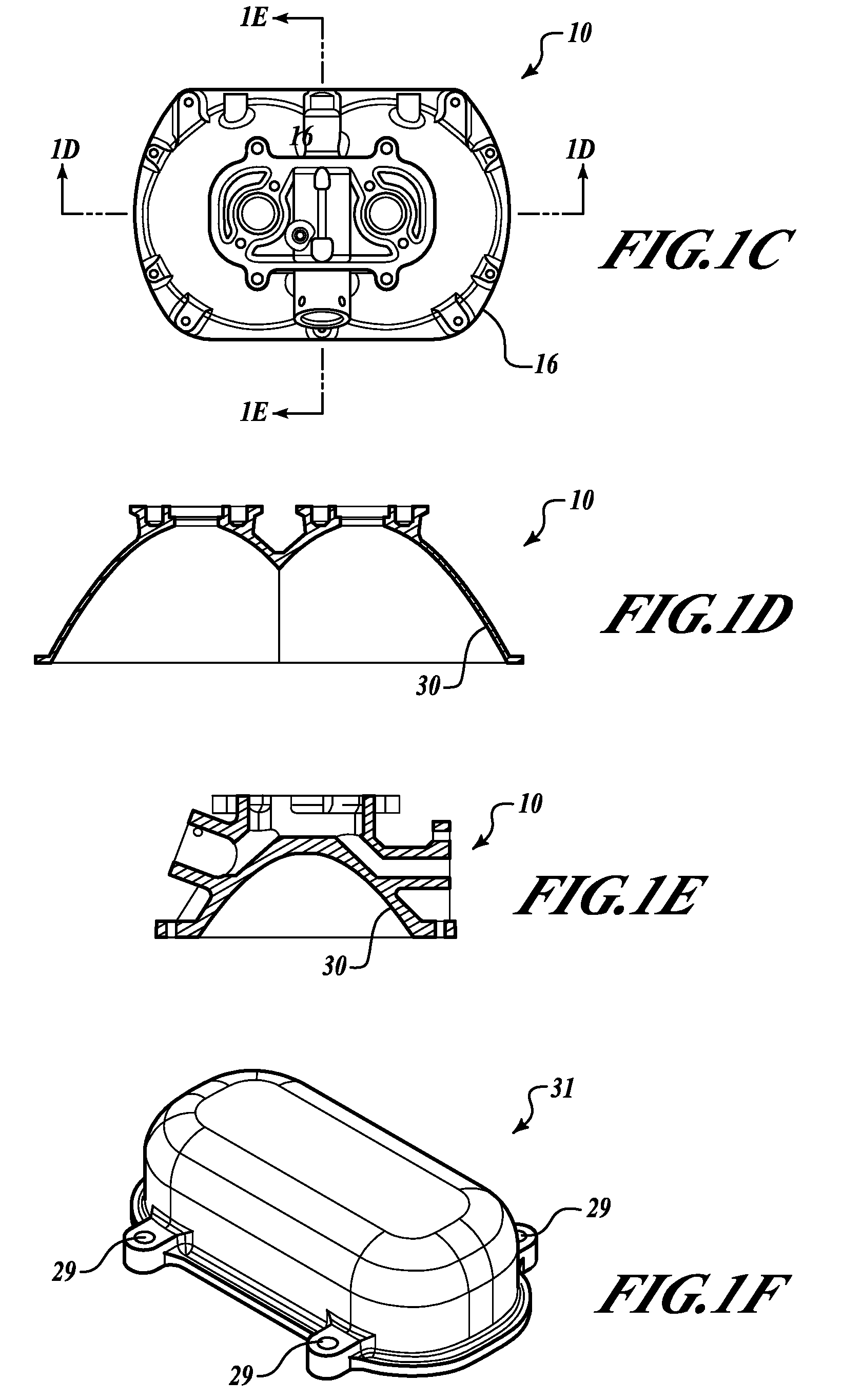
[0024]FIG. 1A shows a housing 10 including a housing rear 12 defining a plurality of lens retainer attachment points 14 located around a housing perimeter 16 (FIG. 1G). The housing rear 12 also defines a searchlight slip ring shaft receptacle 18 and at least one searchlight slip ring shaft attachment point 20. The housing rear 12 also defines a pair of lamp receptacles 22, along with a plurality of lampholder attachment points 24 and housing cover attachment points 26. In FIG. 1B, the housing 10 also defines a plurality of infrared (IR) diode assembly attachment points 28. In FIGS. 1D and 1E, the housing 10 defines a reflector 30. The reflector 30 is cleaned, base coated, and then vacuum metallized. The reflector 30 should have a smooth reflective appearance and show no signs of distortion. The reflector 30 is then coated with aluminum or other suitable material known to those having skill in the art. FIG. 1F shows a housing cover 31 defining a plurality of threaded receptacles 29 t...


PUM


Abstract

A lighthead for a dual-mode searchlight including a generally concave housing with an attached infrared (IR) light source assembly, an insulating barrier and air gap between the visible and IR portions of the assembly, and a reflector integral to the housing.

Description

BACKGROUND OF THE INVENTION[0001]Dual mode searchlights are used in rotorcraft to provide both visible lighting and infrared (IR) lighting modes, depending on the task and conditions the rotorcraft is operating under. U.S. Pat. No. 5,695,272 to Snyder et al. titled “Searchlight For Aircraft And Other Vehicles,” herein incorporated by reference, describes an exemplary visible and infrared lighting element in a lamp head that may be extended, retracted, and rotated. Both light sources, however, are within the same lamp head (and the same lamp face), so that heat generated from the visible light source is not dissipated sufficiently to prevent degradation of the IR light source due to high temperatures generated by the heat from the visible light source. U.S. Pat. No. 6,962,423 to Hamilton et al. titled “Multi-mode Searchlight,” herein incorporated by reference, describes a multi-mode visible and infrared lighthead for use as a landing light or searchlight. The design includes a separa...

Claims


Application Information

Patent Timeline
Patent Type & Authority Patents(United States)
IPC IPC(8): G01J3/10
CPCB64D47/02
Inventor GIFFEN, CRAIG E.MUBASLAT, SAED M.FERGUSON, JOSEPH L.LUNDBERG, JOHN L.
Owner HONEYWELL INT INC
Why Eureka
Try Eureka