Burn-in using system-level test hardware

Inactive Publication Date: 2009-04-14
GLOBALFOUNDRIES INC
View PDF12 Cites 23 Cited by
  • Summary
  • Abstract
  • Description
  • Claims
  • Application Information

AI Technical Summary

Benefits of technology

[0009]In one embodiment, the DUT is coupled to a module that comprises circuitry employed in a product-level application environment. The module is configured by the test controller to simulate a product-level application. During at

Problems solved by technology

Consequently, execution of burn-in and functional tests often requires that a DUT be inserted into each of two or more test fixtures sequentially, resulting in higher risk of damage as well as extending the time to complete all of the tests in the sequence.
The fact that burn-in tests are often performed in a circuit environment that differs from a product-level application may lead to both higher stress to some parts of a device as well as lower stress to other parts than might occur in most applicati

Method used


Image

  • Burn-in using system-level test hardware
  • Burn-in using system-level test hardware
  • Burn-in using system-level test hardware

Examples


Embodiment Construction

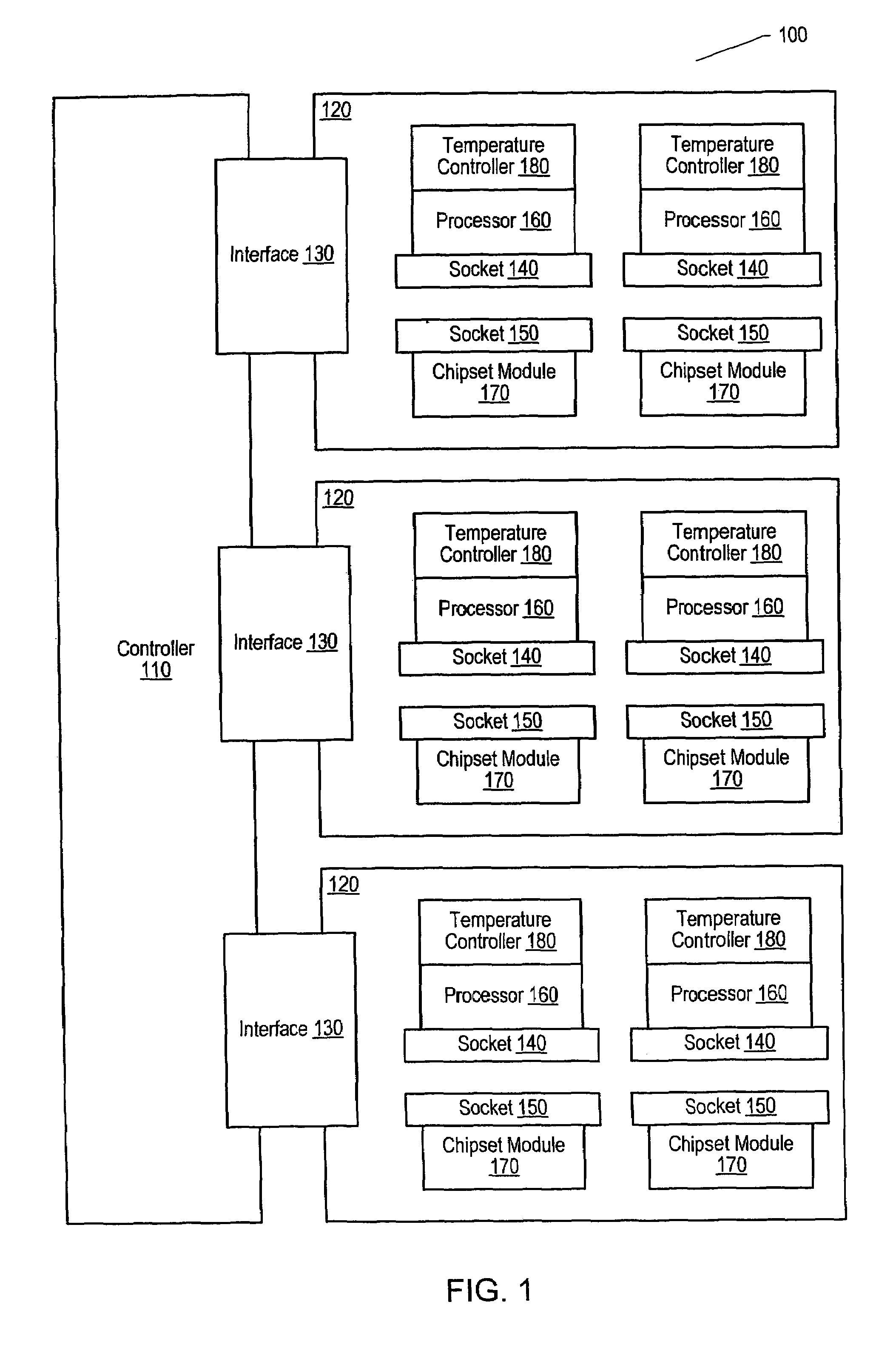
[0016]FIG. 1 illustrates one embodiment of a test system 100 for performing both burn-in and system-level testing. In the illustrated embodiment, a controller 110 is coupled to three device modules 120 via interfaces 130. As shown, each device module 120 includes two sockets 140 and two sockets 150. Socket 140 couples a DUT 160 to device module 120. Socket 150 couples a chipset module 170 to device module 120. DUT 160 is further coupled to a Temperature Controller 180. The number of DUTs 160 and chipset modules 170 that may be coupled to a device module 120 may vary from embodiment to embodiment, depending on physical packaging constraints and the number of simultaneous tests that are desired. Regardless of the number of DUTs 160 on a device module 120, in these embodiments each DUT 160 may be associated with an individual chipset module 170 and an individual temperature controller 180. In addition, in other embodiments, controller 110 may be coupled to more than or less than three ...


PUM


Abstract

A burn-in test system. A burn-in test system includes a device under test (DUT), a temperature controller coupled to the DUT, and a test controller. During testing, the test controller: (a) sets a parameter of the DUT to a first value and applies a test stimulus to the DUT, and (b) sets the parameter of the DUT to a second value and applies the test stimulus to the DUT. A change in the value of the parameter results in a change in the amount of heat dissipated by the DUT. The temperature controller maintains the DUT at a pre-determined temperature during testing with the parameter set to both the first and the second values. The DUT may be further coupled to a module that comprises circuitry employed in a product-level application environment. The module is configured by the test controller to simulate a product-level application.

Description

BACKGROUND OF THE INVENTION[0001]1. Field of the Invention[0002]This invention relates to integrated circuit (IC) test systems and, more particularly, to burn-in and system testing of ICs.[0003]2. Description of the Related Art[0004]Complex integrated circuits (ICs) such as microprocessors are routinely subjected to several tests to screen for defective parts and to characterize the speed and voltage at which they will operate in target applications. One such test that is frequently employed is a “burn-in” test whose purpose is to weed out defective parts that would otherwise fail early in their operating use. Burn-in tests are usually performed on 100% of manufactured parts with the goal of accelerating potential failure mechanisms, thereby screening out any defective parts. In order to accelerate potential failure mechanisms, burn-in testing may operate parts at higher than normal voltages and / or temperatures, with temperatures being controlled by placing parts in an oven-like enc...

Claims


Application Information

Patent Timeline
IPC IPC(8): G01R31/28
CPCG01R31/2874
Inventor JOHNSON, TRENT WILLIAMKLASSEN, STEVEN RUSSELLBRINKLEY, JEFFEUBANK, GLENNYI, JOHN HEONSINGH, SATWANTTARIN, MICHAEL GREGORYPANDYA, CHANDRAKANT
Owner GLOBALFOUNDRIES INC
Why Eureka
Try Eureka