Thermodynamic engine

a technology of thermodynamic engine and engine body, which is applied in the direction of steam engine plants, machines/engines, mechanical equipment, etc., can solve the problems of large amount of unused thermal energy released by the internal combustion engine to the surroundings, and achieve the effect of avoiding overheating, eliminating the catalytic effect, and optimum overall efficiency

Inactive Publication Date: 2009-04-21
BAYERISCHE MOTOREN WERKE AG
View PDF15 Cites 26 Cited by
  • Summary
  • Abstract
  • Description
  • Claims
  • Application Information

AI Technical Summary

Benefits of technology

[0003]The invention proceeds from WO 02 / 31320 A1. The cited document describes a thermodynamic engine for an internal combustion engine which operates according to the Rankine cycle process. The thermodynamic engine is characterized by the fact that it comprises two parallel Rankine cycle processes, in each of which a pump first transports a liquid through a heat exchanger located on an exhaust gas train of an internal combustion engine, the liquid being evaporated, further transported into a decompression device in which the superheated vapor drives a vane pump, and further transported into a condenser in which the residual vapor is condensed. The liquid then flows back through the same circuit. To improve the efficiency of the thermodynamic engine, liquids with different boiling points are used in the circuits. In a proposed embodiment, the circuit with its heat exchanger located closer to the internal combustion engine receives the liquid having the higher boiling temperature. This circuit is a high-temperature circuit, whereas the second circuit is a low-temperature circuit. In order to maintain the efficiency of the high-temperature circuit at a high level, its pump is a variable feed pump.
[0014]A partial vacuum may be created in the condenser, using the arrangement of an additional pump in the low-temperature circuit between the condenser and the first collection container. This partial vacuum causes the first working medium to liquefy at even lower temperatures and subsequently be further pumped into the first collection container. The efficiency of the low-temperature circuit is improved even more by use of the third pump.

Problems solved by technology

Although the efficiency of the thermodynamic engine is improved by the above-mentioned measures, the internal combustion engine still releases a large amount of unused thermal energy to the surroundings.

Method used


Image

  • Thermodynamic engine
  • Thermodynamic engine

Examples


Embodiment Construction

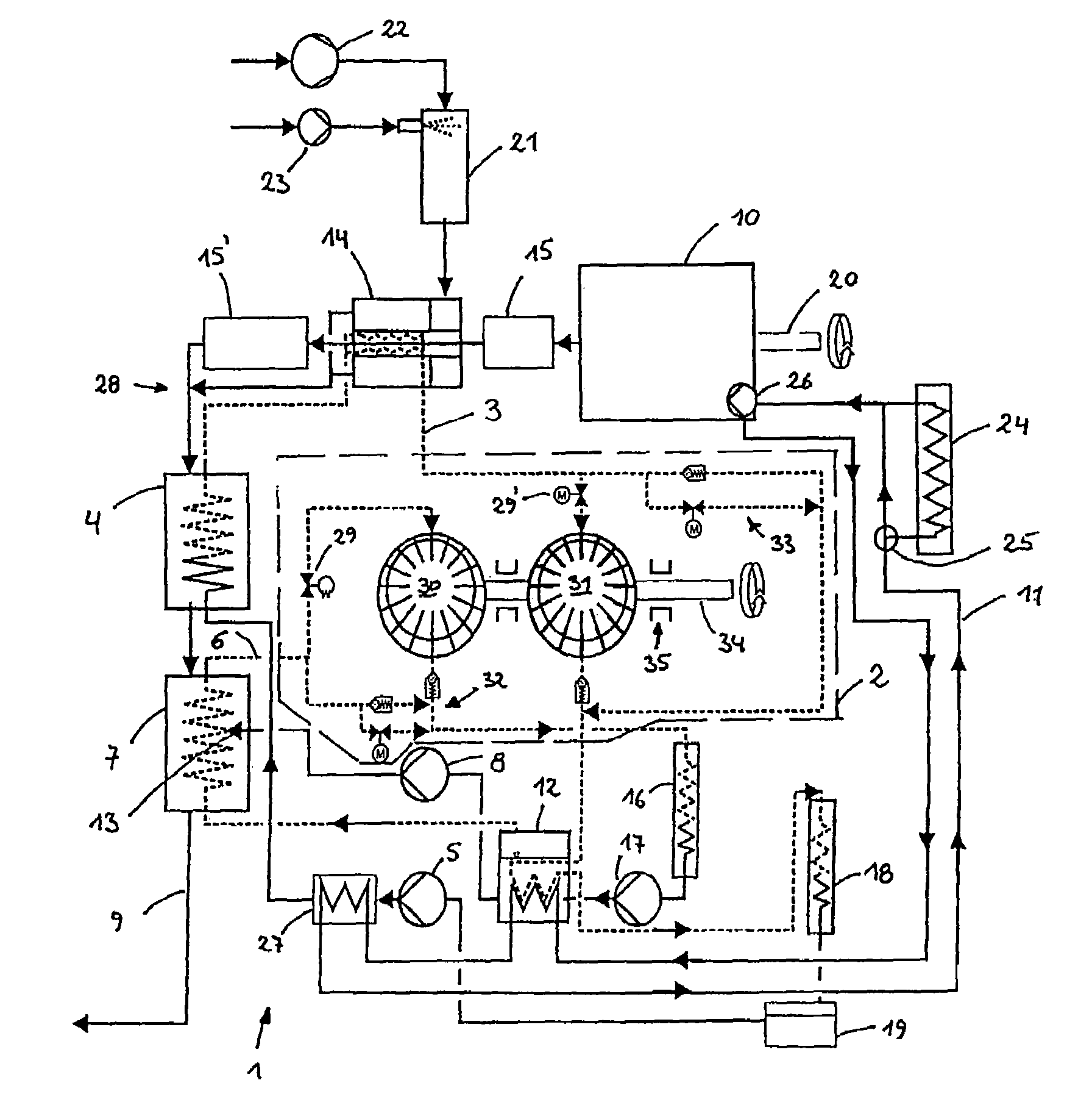
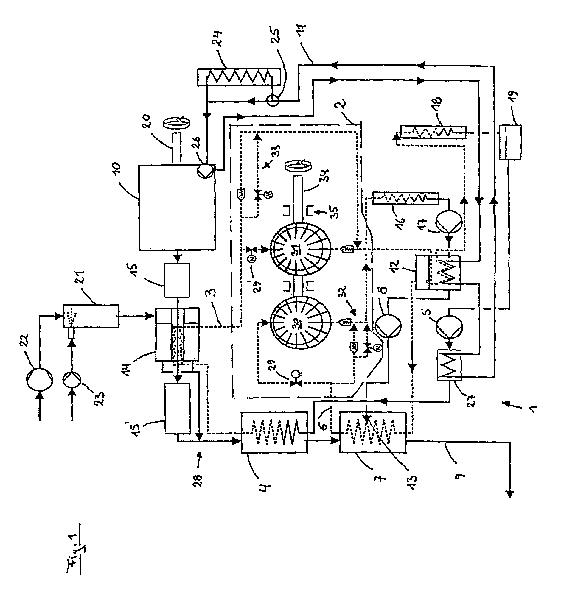
[0017]FIG. 1 schematically shows an internal combustion engine 10, the output power of which is supported at a first output shaft 20 by a thermodynamic engine 1. The internal combustion engine 10 has an exhaust gas system 9 for removal of exhaust gases. The exhaust gas system 9 is represented by arrows in the direction of flow of the exhaust gas. Two catalytic cleaning devices 15, 15′ are integrated into the exhaust gas system 9. Catalytic cleaning device 15 is a precatalyst, and catalytic cleaning device 15′ is a main catalyst. The thermodynamic engine 1 essentially comprises two separate Rankine circuits, a closed low-temperature circuit 6 and a closed high-temperature circuit 3. In the low-temperature circuit 6 a third pump 17 transports a first working medium into a first collection container 12. The liquid first working medium is indicated by a solid line, and the vaporous working medium is indicated by a dotted line. The first working medium is temporarily stored in both liqui...


PUM


Abstract

A thermodynamic engine converts the superheated steam of at least one working medium into kinetic energy using a decompression device. Said engine includes a low-temperature circuit, in which a first working medium is transported through a first heat exchanger and subsequently through the decompression device and a high-temperature circuit, in which a second working medium is transported through a second heat exchanger and subsequently through the decompression device. The first heat exchanger and the second heat exchanger are located in the exhaust system of an internal combustion engine, and the internal combustion engine a coolant circuit can be used to heat the working mediums in separate collection containers.

Description

[0001]This application is a continuation of International Patent Application No. PCT / EP2003 / 011731, filed Oct. 21, 2003, the entire disclosure of which is incorporated herein by reference. Priority is claimed based on German Patent Application No. 102 59 488.0, filed Dec. 19, 2002.BACKGROUND AND SUMMARY OF THE INVENTION[0002]The invention relates to a thermodynamic engine employing superheated vapor to generate kinetic energy.[0003]The invention proceeds from WO 02 / 31320 A1. The cited document describes a thermodynamic engine for an internal combustion engine which operates according to the Rankine cycle process. The thermodynamic engine is characterized by the fact that it comprises two parallel Rankine cycle processes, in each of which a pump first transports a liquid through a heat exchanger located on an exhaust gas train of an internal combustion engine, the liquid being evaporated, further transported into a decompression device in which the superheated vapor drives a vane pum...

Claims


Application Information

Patent Timeline
Patent Type & Authority Patents(United States)
IPC IPC(8): F01K23/10F01K23/06F02G1/04F02G5/02F02G5/04
CPCF01K23/065F02G1/04F02G5/02F02G5/04Y02T10/166Y02T10/12
Inventor HOETGER, MICHAELCLEMENS, HERBERTHAAS, TOBIASFREITAG, GUNNARPREIS, MICHAELFREYMANN, RAYMONDOBIEGLO, ANDREAS
Owner BAYERISCHE MOTOREN WERKE AG
Why Eureka
Try Eureka