Method of controlling the injection of liquid into an inflow duct of a prime mover or driven machine

a technology of inflow duct and driven machine, which is applied in the manufacture of engines, machines/engines, mechanical apparatus, etc., can solve the problems of reducing affecting the efficiency of compression, and requiring a greater proportion of turbine work, so as to achieve the effect of reducing the pressure difference over the injection nozzle, reducing the pressure difference, and improving the efficiency of compression

Inactive Publication Date: 2009-04-21
ANSALDO ENERGIA IP UK LTD
View PDF183 Cites 36 Cited by
  • Summary
  • Abstract
  • Description
  • Claims
  • Application Information

AI Technical Summary

Benefits of technology

[0013]In an embodiment of the invention, the supply lines of the nozzles and / or tubes combined to form a group are brought together at a point situated upstream in such a way that all the nozzles and / or tubes of the group can be activated via a common shut-off member. In this case, the admission of liquid to individual nozzles and / or tubes via in each case separate shut-off members ensures greater flexibility of the injection pattern to be realized, whereas the activation of an entire group via a common shut-off member leads to a simplification in terms of equipment and control.
[0014]In a preferred embodiment of the invention, the pressure difference over the injection nozzles is kept constant. The liquid mass flow, in good approximation, is then proportional to the entire nozzle cross section to which liquid is admitted; provided that all the nozzles are identical, which is an advantageous aim, the liquid mass flow is proportional to the number of nozzles to which liquid is admitted. In a preferred embodiment, all the nozzles have an identical throughflow behavior. Furthermore, in one embodiment, all the tubes have an identical nozzle complement. The injected liquid mass flow is then proportional to the number of nozzles and / or tubes to which liquid is admitted. If this is not the case, an individual partial mass flow may be assigned to each tube. If pressure atomizer nozzles are used for spraying the liquid, the pressure drop over the nozzles is as a rule around a few 10 bar, for example 30-50 bar. In contrast, the pressure change in the inflow duct is negligible, so that it is sufficient as a rule for the supply pressure of the liquid in the tubes or in the feed line system to the nozzles and / or tubes to be kept constant. As a result, the mass flow delivered by a liquid pump can be controlled very simply in such a way that the supply pressure remains constant.
[0019]With the present method, it is possible to graduate the injection quantity of the cooling medium in such a way as to be adapted to the operating mode, in particular the respectively deliverable or required output, of the prime mover or driven machine during operation thereof. Thus the various injection groups, to which the various injection nozzles are assigned, are switched on and / or off during the operation for increasing or reducing the cooling capacity in such a way that the change in the quantity of the injected cooling medium is possible in small steps from stage to stage, and consequently finely graduated mass flow desired values can be delivered.

Problems solved by technology

This has various adverse consequences at the compressor of a gas turboset.
The increased inlet temperature at the combustor can result in lower firing of the gas turboset.
The compression requires a greater proportion of the turbine work and takes place at a poorer efficiency.
Consequently, the output and efficiency potentials of the gas turboset are adversely affected.
However, since permanent water injection could lead to problems on account of blade erosion, the sprayed liquid must be atomized very finely into very small droplets.
Therefore the challenge with corresponding technical solutions has hitherto been to realize water spraying with very small droplets, normally 0.9-5 μm in diameter during “flash atomization” and 20-40 μm during high-pressure atomization.
This means that the evaporation has to be effected within milliseconds.
On the other hand, the profile of the droplet load of the intake air may greatly vary and have steep gradients due to the switching-on and switching-off of various nozzle groups.
A distribution which is very uneven results in locally varying cooling in the compressor.
The resulting warm and cold strands reduce the pumping distance (surge margin) of the compressor and in the extreme case may lead to the distortion of the casing.

Method used


Image

  • Method of controlling the injection of liquid into an inflow duct of a prime mover or driven machine
  • Method of controlling the injection of liquid into an inflow duct of a prime mover or driven machine
  • Method of controlling the injection of liquid into an inflow duct of a prime mover or driven machine

Examples


Embodiment Construction

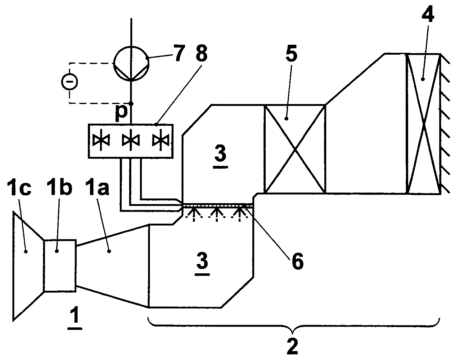
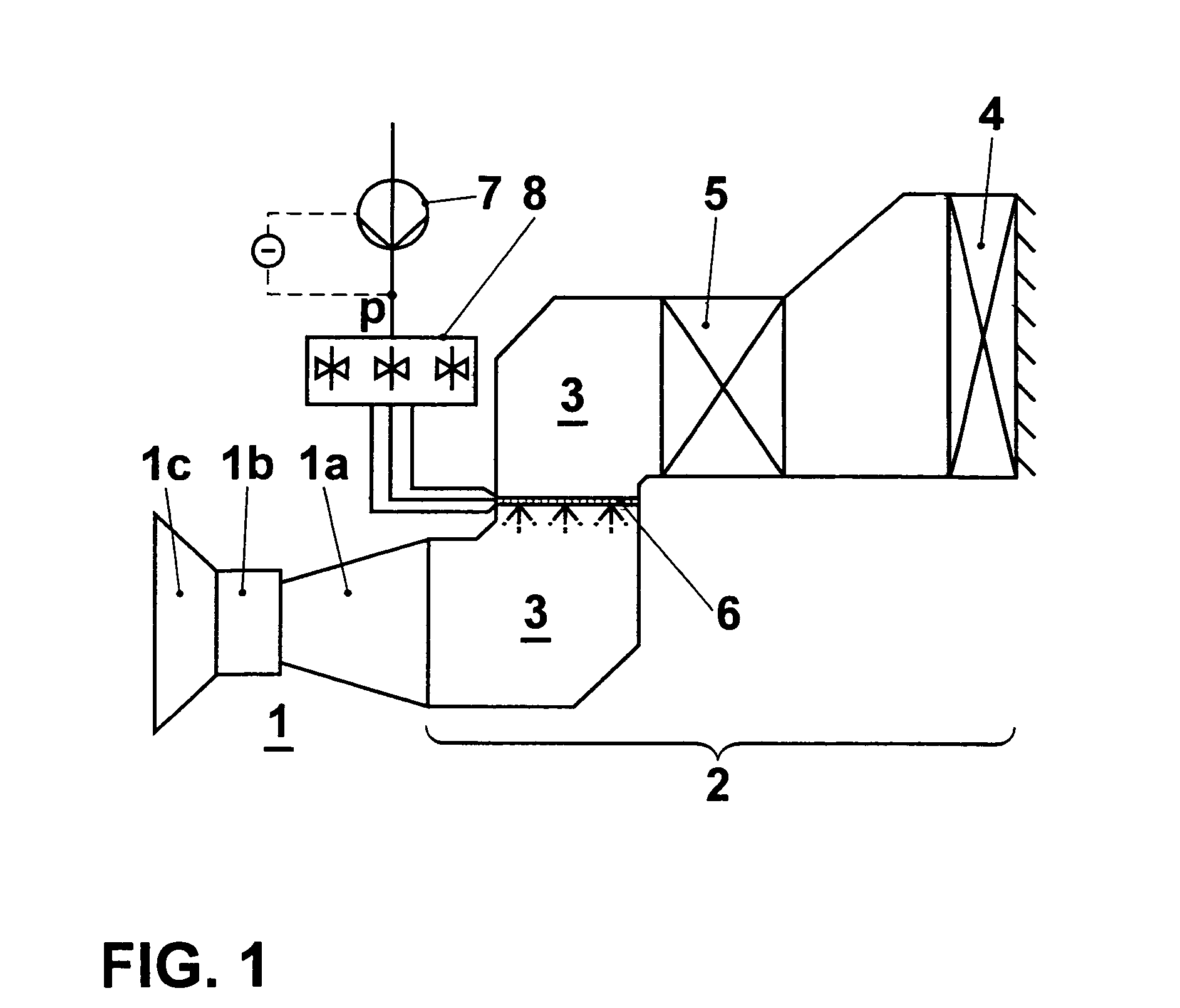
[0027]FIG. 1 schematically illustrates the use of the method according to the invention with reference to the inflow duct of a gas turboset 1. The gas turboset shown by way of example has, without restricting the universality, a compressor 1a, a combustor 1b and a turbine 1c. Connected upstream of the compressor is an intake region 2 for preparing the intake air fed in the inflow duct 3. An air filter 4 and an intake silencer 5 are arranged in the intake region. A device 6 for injecting a liquid into the inflow duct 3 is arranged downstream of the intake silencer. This device serves in particular to introduce finely atomized liquid water droplets into the compressor 1a, where, as mentioned at the beginning, they evaporate and thereby internally cool the compressor. Downstream of this injection device, built-in components of large area are no longer arranged in the flow path up to the compressor inlet, apart from some bearing supports which are known from the prior art, but which onl...


PUM


Abstract

The injection of finely atomized liquid-droplets into the intake air flow of a compressor is used, for example, to improve the output of a gas turbine. If the atomization is effected via pressure atomizer nozzles, it is advantageous, when the injection device is operated with a portion of the design mass flow, to admit liquid to only some of the atomizer nozzles of the injection device. The atomizer nozzles may be arranged on nozzle tubes, liquid being jointly admitted to all the atomizer nozzles arranged on a respective nozzle tube, operated in such a way that the same mass flow is injected on each side of a symmetry line. To this end, nozzle tubes may be combined to form groups, to which liquid is jointly admitted, and the tubes of a group may be arranged in mirror image to one another relative to the symmetry line.

Description

CROSS-REFERENCE TO RELATED APPLICATIONS[0001]This application is a continuation of the U.S. National Stage designation of co-pending International Patent Application PCT / EP2003 / 050901 filed Nov. 26, 2003, which claims priority to German patent application no. 102 56 193.1 filed Dec. 2, 2002, and the entire contents of these applications are expressly incorporated herein by reference thereto.FIELD OF THE INVENTION[0002]The invention relates to a method of controlling the injection of liquid into an inflow duct of a prime mover or driven machine, and also relates to a device for carrying out the method.BACKGROUND OF THE INVENTION[0003]A gas is heated during its adiabatic compression. Due to the heating and the associated increase in volume, the requisite compression work is increased. This has various adverse consequences at the compressor of a gas turboset. The increased inlet temperature at the combustor can result in lower firing of the gas turboset. The compression requires a grea...

Claims


Application Information

Patent Timeline
Patent Type & Authority Patents(United States)
IPC IPC(8): F02C3/30F02C7/143
CPCF02C7/1435Y02T50/676F05D2260/212F05D2250/51Y02T50/60
Inventor HOFFMANN, JUERGENMATZ, CHARLES RAYMOND
Owner ANSALDO ENERGIA IP UK LTD
Why Eureka
Try Eureka