Retractable leg assembly for amphibious vehicle

a technology for amphibious vehicles and legs, applied in the direction of item transportation vehicles, vehicle carriers, floating buildings, etc., can solve the problems of inability of vehicles to retract or extend their wheels, inability to achieve the effect of reducing operator workload and reducing steering system complexity

Active Publication Date: 2009-04-21
SEALEGS INT
View PDF7 Cites 14 Cited by
  • Summary
  • Abstract
  • Description
  • Claims
  • Application Information

AI Technical Summary

Benefits of technology

[0009]It is therefore an object of the present invention to provide a retractable leg assembly which will at least go some way towards overcoming the above mentioned problems, or at least provide the public with a useful choice.

Problems solved by technology

Amphibious vehicles have a number of design challenges, the majority of which centre around the problem of translating the wheels from a deployed position to and from a retracted position.
These diverse requirements have often lead to designs which use significant amounts of space within the vehicle to stow the wheels, and / or have complex systems with doors and seals through which the wheels pass, and when steering is also incorporated, complex methods to engage with some sort of steering system are employed.
Another limitation of previous designs is an inability of the vehicles to retract or extend their wheels when on dry ground, for example to beach the vehicle, or to raise it off the ground again.
This complexity, sometimes coupled with poor use of space, has prevented most of the previous designs from ever becoming a commercial success.
Complexity will not only drive costs higher, but also becomes a maintenance burden that is aggravated by operations in salt or fresh water.

Method used


Image

  • Retractable leg assembly for amphibious vehicle
  • Retractable leg assembly for amphibious vehicle
  • Retractable leg assembly for amphibious vehicle

Examples


example 1

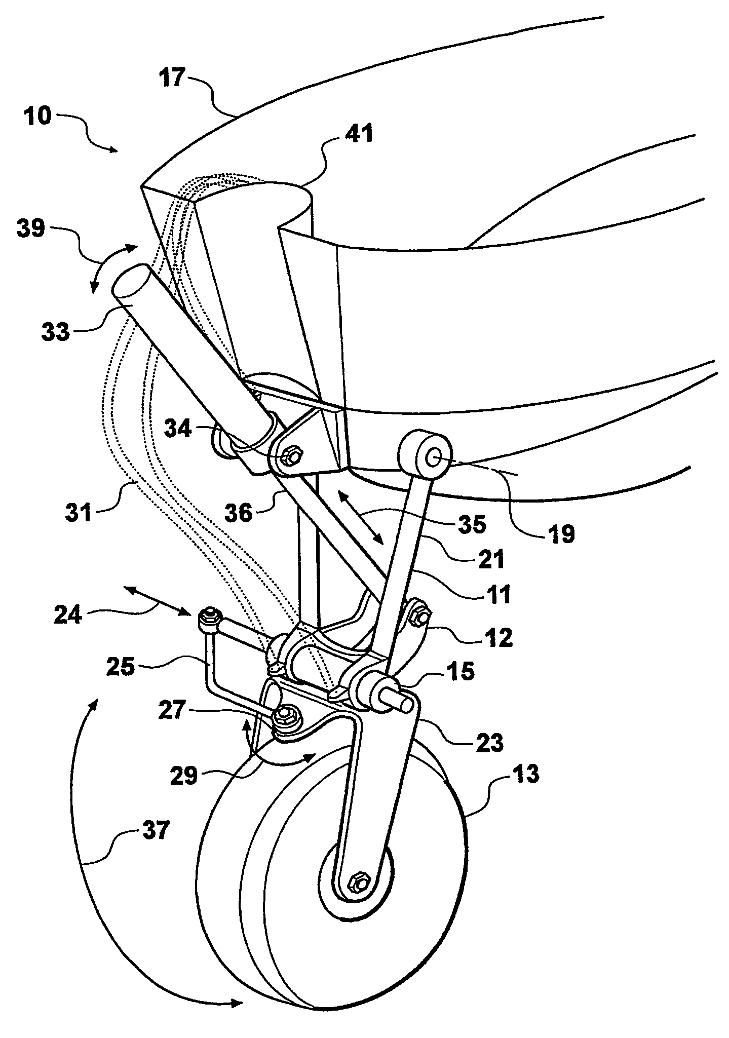
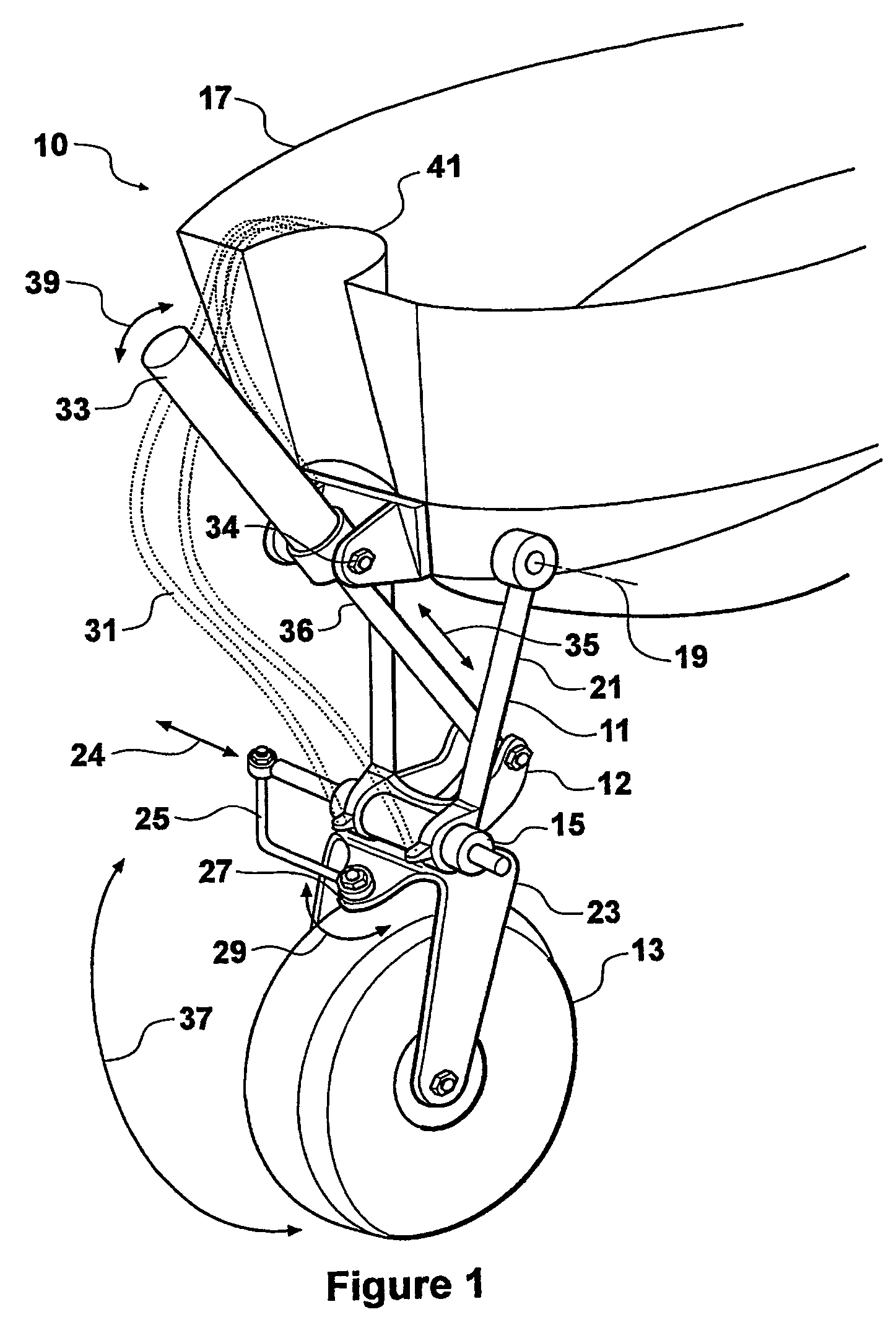
[0050]With reference to FIG. 1, a first example of a steerable and retractable leg assembly (10) is shown comprising a leg (11), a wheel (13) and a steering actuator (15). The leg (11) is shown pivotally mounted to the hull (17) of an amphibious vehicle via bearings (not shown) mounted in the hull (17) arranged about axis (19). In this example a shaft extends from one side of the hull (17) to the other, and the leg is supported by two bearings, one mounted within each side of the hull (17).

[0051]In the preferred form the axis (19) is above the waterline of the amphibious vehicle.

[0052]The leg (11) comprises a substantially triangular shaped upper frame assembly (21) and a yoke assembly (23). The yoke assembly (23) is pivotally mounted to the upper frame assembly (21) to allow steering of the wheel (13). To effect controlled steering of the wheel (13), the steering actuator (15) is provided. The steering actuator (15) is mounted onto the upper frame assembly (21) and acts via a conne...

example 2

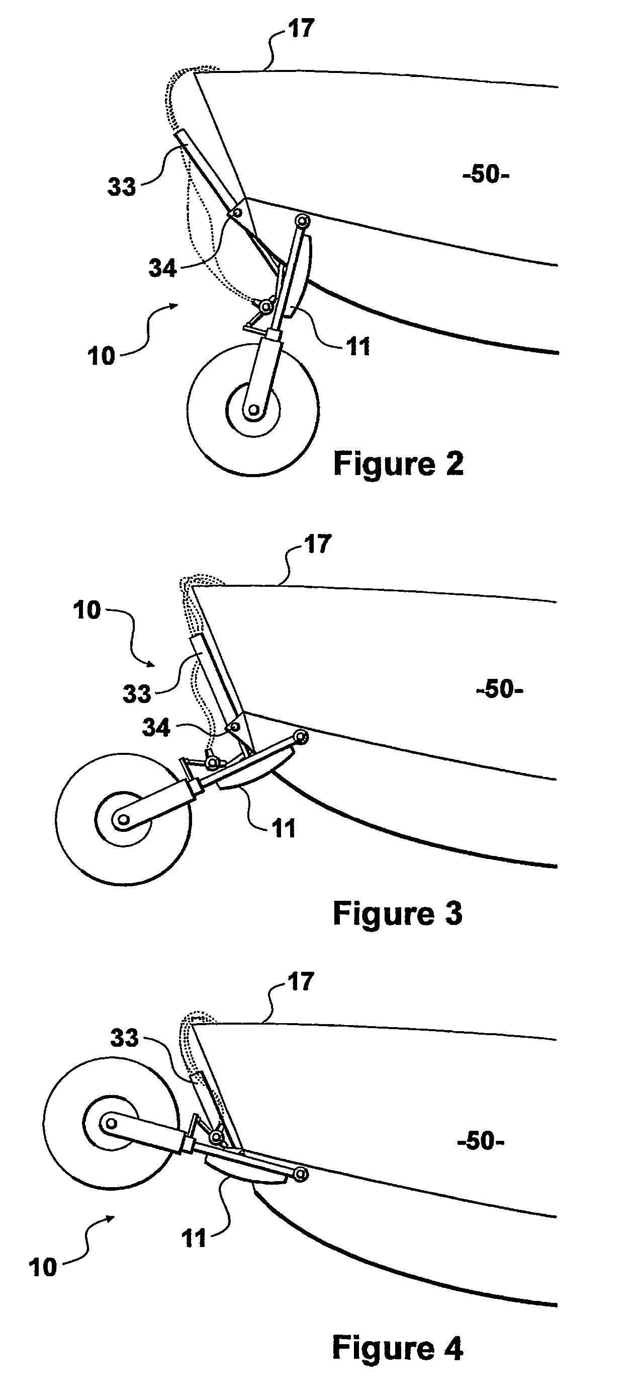
[0065]With reference to FIG. 7, a second example of a steerable and retractable leg assembly (100) is shown comprising a leg (11), an adapter fitting (113), a retract actuator (115) and a steering actuator (117). The leg assembly (100) can be mounted to the hull of an amphibious vehicle by bolting the adapter fitting (113) to the hull of the vehicle. The retract actuator (115) is adapted to move the leg (111) through an arc of movement from a retracted position to an extended position and in the return direction. The leg (111) moves through an arc of just over 120 degrees when moving from the retracted position to the extended position.

[0066]Such a range of movement is advantageous in this application since the leg (111) must be oriented close to vertical when in the extended position to provide adequate ground clearance for an amphibious vehicle to which it is attached, and yet the leg (111) must be oriented well above a horizontal attitude when in the retracted position to keep it...


PUM


Abstract

Leg assembly (10) for an amphibious vehicle comprises leg (11) and hydraulic ram (33) each pivotally mounted, above the waterline, externally to hull (17). The line of action of ram (33) is such that it is optimal (eg less than 30 DEG) with respect to the tangent to the arc of travel of leg (11) when it is lowered or raised. Leg (11) carries wheel (13) which may be swivelled for steering using hydraulic linear actuator (15). Assembly (10) is compact, light, yet capable of lifting the vehicle off the ground.

Description

BACKGROUND OF THE INVENTION[0001]1. Field of the Invention[0002]This invention relates to a retractable leg assembly, and in particular, a retractable and steerable leg assembly for use with an amphibious vehicle.[0003]2. Description of the Related Art[0004]Numerous attempts have been made to produce leg assemblies that are suitable for amphibious vehicles. Amphibious vehicles have a number of design challenges, the majority of which centre around the problem of translating the wheels from a deployed position to and from a retracted position.[0005]For the amphibious vehicle to work well on the water, the wheels should be well out of the way, and the hull should retain fairly clean lines, so that drag is minimised. And yet when the vehicle is to be used on land, the tires must be of a suitable size, adequate ground clearance is required, and a method of steering is required.[0006]These diverse requirements have often lead to designs which use significant amounts of space within the v...

Claims


Application Information

Patent Timeline
Patent Type & Authority Patents(United States)
IPC IPC(8): B60P3/10B63C13/00
CPCB60F3/003B63C13/00B60F2301/04
Inventor BRYHAM, MAURICE JOHN
Owner SEALEGS INT
Why Eureka
Try Eureka