
Blood pressure measuring apparatus

a technology of measuring apparatus and blood pressure, which is applied in the field of blood pressure measuring apparatus, can solve the problems of increasing the errors of blood pressure values, affecting the accuracy of blood pressure measurement, so as to suppress the reduction of accuracy and high speed

Active Publication Date: 2009-04-21
FUKUDA DENSHI CO LTD
View PDF11 Cites 21 Cited by
  • Summary
  • Abstract
  • Description
  • Claims
  • Application Information

AI Technical Summary

Benefits of technology

The present invention is a blood pressure measuring apparatus that can quickly and accurately measure blood pressure. It uses a cuff to measure pressure and a special algorithm to calculate the blood pressure based on the change in pressure and the maximum amplitude of the pulse waves. This allows for quick blood pressure readings while maintaining accuracy. The invention can be used in a medical apparatus for blood pressure measurement. Overall, the technical effect of the invention is to provide a reliable and efficient tool for blood pressure measurement.

Problems solved by technology

The automated blood pressure measuring apparatus by the oscillometric technique are widely used since a blood pressure can be measured relatively easily, however, they require a certain time for measurement.
In order to shorten the time for measurement, a cuff deflation rate after avascularization needs to be increased; however, the increased cuff deflation rate makes it difficult to detect the maximum amplitude of pulse waves with high accuracy, which in turn results in increasing errors in blood pressure values.
Meanwhile due to the above factors the increased deflation rate makes it difficult to detect the maximum amplitude with high accuracy, there is a demand from subjects for quick release from the pressure by a cuff after avascularization because the pressure is not comfortable.

Method used


Image

  • Blood pressure measuring apparatus
  • Blood pressure measuring apparatus
  • Blood pressure measuring apparatus

Examples


example

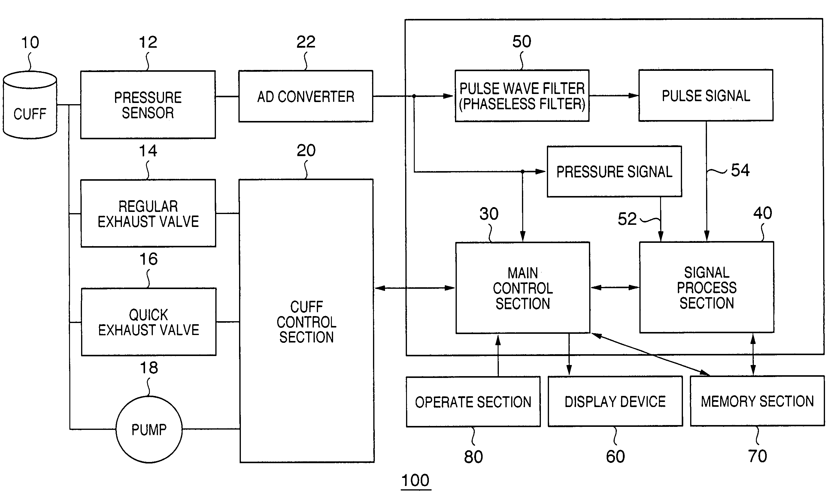
[0065]In a blood pressure measuring apparatus having a configuration of FIG. 1, a phaseless filter configured with a high-pass filter and a low-pass filter having the characteristics of Formula (3) below was used as the pulse wave filter 50. A blood pressure was actually measured using the lower formula of Formula (2′) as a condition to determine a blood pressure, with a deflation rate of a cuff pressure by opening the regular exhaust valve 14 being 10 mmHg / second, a sampling period by the AD converter 22 being 4 ms. The constant a in the Formula to determine a diastolic blood pressure was 20.

[0066]HPF⁢⁢Pulse⁡(i)=P⁡(z-199-(1200·1-z-2001-z1)2)⁢⁢LPF⁢⁢Pul⁡(i)=Pulse⁡(i)⁢(17·1-z-71-z-1)3[Formula⁢⁢3]

[0067]About 1300 measurements were performed, and as a result the difference to the measurement value with a direct method is: mean error −3.68 mmHg and standard deviation 7.56 mmHg for systolic blood pressure; and mean error 3.28 mmHg and standard deviation 5.9 mmHg for diastolic blood pressu...


PUM


Abstract

A blood pressure measuring apparatus to measure blood pressure based on a change in a pressure by a cuff mounted to a subject comprises: cuff pressure controlling means for deflating the cuff after avascularization by the cuff at a body part around which the cuff is placed; detecting means for detecting the change in a pressure by the cuff and outputting the detection as an electrical signal; extracting means for extracting a pulse wave signal from the electrical signal; and calculating means for calculating a systolic blood pressure value and a diastolic blood pressure value based on a relation between a change rate of an index value which is calculated by multiplying a maximum amplitude of each pulse of the pulse wave signal by the cuff pressure corresponding to the maximum amplitude and a predetermined value. The blood pressure measuring apparatus achieves a high-speed measurement while suppressing the reduction of accuracy.

Description

CLAIM OF PRIORITY[0001]This application claims priority from Japanese Patent Application No. 2005-075512, filed on Mar. 16, 2005, which is hereby incorporated by reference herein.FIELD OF THE INVENTION[0002]The present invention relates to a blood pressure measuring apparatus, in particular, to an automated blood pressure measuring apparatus using a cuff.BACKGROUND OF THE INVENTION[0003]Conventionally, an oscillometric technique is known to measure blood pressure non-invasively. In the oscillometric technique, a cuff is fitted around a limb such as a brachium of a subject to detect pulse waves at the body part by the cuff and a blood pressure is measured based on the fact that the volume of the blood vessel under the cuff changes most at the point when the pressure applied by the cuff to the blood vessel becomes equal to a mean blood pressure thereof.[0004]Specifically, the cuff is inflated to press the body part for avascularization, and as the cuff is being deflated, the cuff pres...

Claims


Application Information

Patent Timeline
Patent Type & Authority Patents(United States)
IPC IPC(8): A61B5/00
CPCA61B5/02116A61B5/02225A61B5/0225
Inventor NUNOME, TOMOHIRO
Owner FUKUDA DENSHI CO LTD
Learn More