
Coated high temperature superconducting tapes, articles, and processes for forming same

a technology of superconducting tapes and coatings, applied in the direction of superconducting devices, permanent superconductor devices, coatings, etc., can solve the problems of high cost of materials and the process used to manufacture them, and inability to meet the requirements of us

Inactive Publication Date: 2009-04-21
SUPERPOWER INC
View PDF11 Cites 10 Cited by
  • Summary
  • Abstract
  • Description
  • Claims
  • Application Information

AI Technical Summary

Benefits of technology

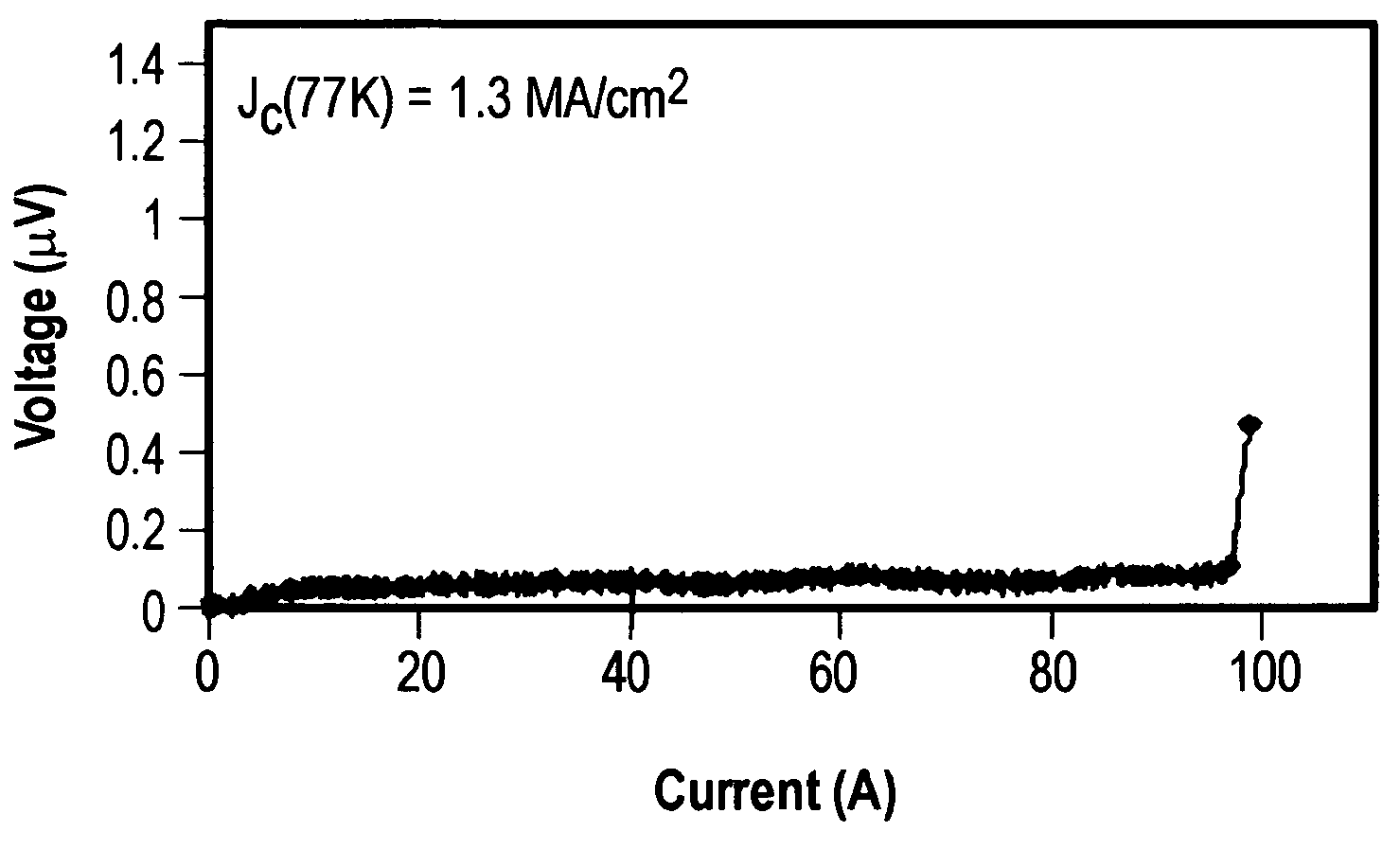
The CVD process achieves critical currents of about 100 A / cm width at 77K and self-field, exceeding the performance of existing BSCCO-based HTS tape technology, making it suitable for electric power applications and enabling commercially viable HTS conductor production.

Problems solved by technology

This material and the process used to manufacture it have proven to be expensive.
Furthermore, the properties of this material degrade quickly in the presence of magnetic fields that are generated in a number of electric power devices.
However, these techniques are limited in several ways.
First, they are all limited by line of sight i.e., the vapors can coat the substrate only where they can ‘see’ the substrate, which means that the coated area is small.
This limits the throughput of coated tape.
Second, the composition of the coated film is limited to the composition of the material being vaporized.
Third, the source material has to be maintained under vacuum causing refill to be difficult and in turn poses a problem for long-length manufacturing.
Fourth, the source material has to be formed into a monolith, which adds cost to the process.
Fifth, a high vacuum is needed which increases cost of capital equipment
However, wet chemical processes have limitations including rate of conversion of precursor to film, thickness control, need for multiple steps for film formation (deposition, bakeout, & heat treatment as a minimum), need for repeating these multiple steps multiple times to build thick films, carbon residue incorporation in the films, difficulties in epitaxial growth in thick films, and evolution of harmful byproducts such as HF if fluorinated precursors are used.
However, MOCVD has yet to be shown to be a viable approach to achieve high current and high current density with HTS Coated conductors because suitable MOCVD apparatuses and processes have not been developed.

Method used


Image

  • Coated high temperature superconducting tapes, articles, and processes for forming same
  • Coated high temperature superconducting tapes, articles, and processes for forming same
  • Coated high temperature superconducting tapes, articles, and processes for forming same

Examples


example

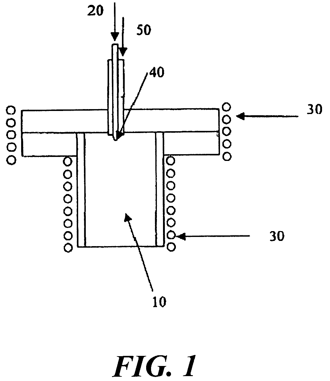
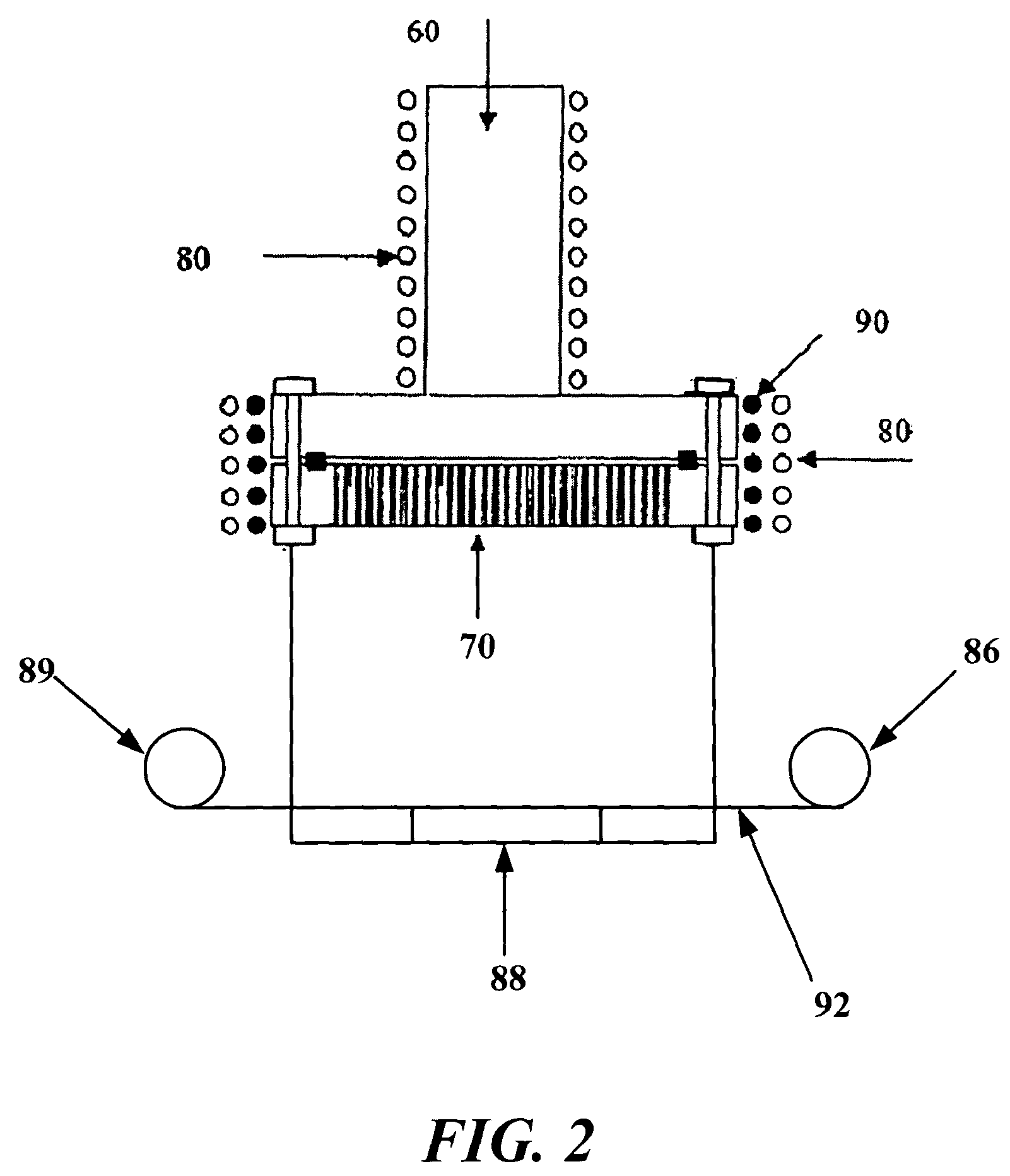
[0081]Tetramethyl heptanedionates of yttrium, barium [adducted with phenanthroline] and copper are obtained from Inorgatech, Mildenhall, Suffolk, U.K. The Y compound is dissolved in solvent containing 2 parts of THF and 1 part isopropanol. The Ba compound is dissolved is a solvent containing 3.5 parts THF and 1 part isopropanol. The Cu compound is dissolved only in THF. The molarity of overall solution is 0.03 M / l.

[0082]The liquid components are combined at room temperature in an ultrasound mixer in the ratio of 1 part Y composition, 2.15 parts Ba composition and 3 parts Cu composition. The mixed liquid precursor is pumped at a rate of 0.25 ml / min through a HPLC pump. From the pump, the precursor is pumped through 0.0625″ OD, 0.010″ ID stainless steel tubing at a pressure of 5 psi to the vaporizer.

[0083]The mixed component precursor enters the vaporizer through the nozzle that is made from a 0.0625″ OD, 0.01″ ID tubing swaged to an ID of 0.004″ at tip. The tip is placed in a vaporiz...


PUM

PropertyMeasurementUnit
temperatureaaaaaaaaaa
pressureaaaaaaaaaa
temperatureaaaaaaaaaa

Abstract

A superconducting article is disclosed, including a substrate and a chemical vapor deposited thin film superconducting layer overlying the substrate, the superconducting layer having a critical current not less than about 100 A / cm width at 77K and self field. The superconducting article may be a tape, multiple tapes, or a power device, such as a power cable, power generator, or power transformer. Also disclosed are methods for manufacturing same and methods for using same.

Description

CROSS-REFERENCE TO RELATED APPLICATION(S)[0001]The present application is related to and claims benefit of priority to U.S. patent application Ser. No. 10 / 344,169, filed Feb. 7, 2003, which is the U.S. National Stage Application of and claims priority to PCT / US01 / 41529, filed Aug. 3, 2001 (published WO / 02 / 056420 on Jul. 18, 2002), which in turns claims priority to U.S. Provisional Patent Application 60 / 223,175, filed Aug. 7, 2000. Priority is claimed to each of the foregoing applications.BACKGROUND[0002]1. Field of the Invention[0003]This invention relates generally to high temperature superconducting materials, components and articles incorporating same, and processes for forming same.[0004]2. Description of the Related Art[0005]High temperature superconducting (HTS) materials have immense potential for use in electric power, electronics, and medical industries. Presently, the HTS material that is manufactured in considerable quantities by industry is based on (Bi,Pb)SrCaCuO (BSCCO...

Claims


Application Information

Patent Timeline
Patent Type & Authority Patents(United States)
IPC IPC(8): B05D5/12H01L39/24C23C16/40C23C16/448C23C16/455H10N60/01H10N60/20
CPCC23C16/408C23C16/4481H01L39/2441H01L39/143Y10T29/49014H10N60/203H10N60/0464C23C16/40
Inventor SELVAMANICKAM, VENKAT
Owner SUPERPOWER INC
Learn More