Optical waveguide and the method of fabricating the same
a technology of optical waveguides and optical waveguides, applied in the field of optical waveguides, can solve problems such as reducing the curing
- Summary
- Abstract
- Description
- Claims
- Application Information
AI Technical Summary
Benefits of technology
Problems solved by technology
Method used
Image
Examples
example 1
Measurement of a Refractive Index
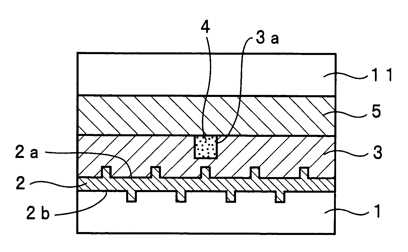
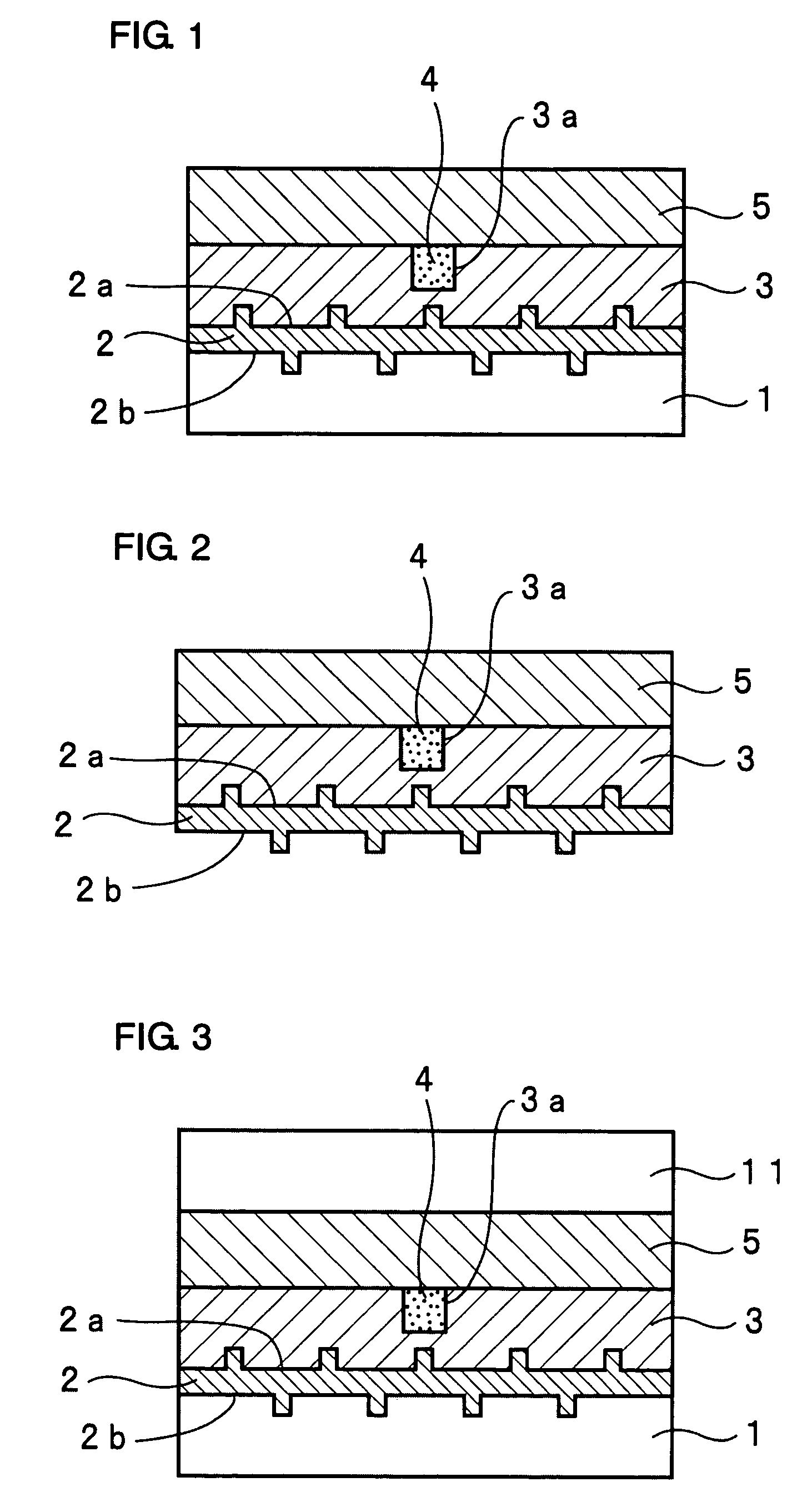
[0113]In order to evaluate the effects of providing the ultraviolet control region 2 on the control of refractive index in the lower clad layer 3 in the embodiment shown in FIG. 1, an ultraviolet control region 2 was formed on each substrate 1 using substrates 1 having different thicknesses, and a lower clad layer 3 was formed on the ultraviolet control region 2, and a refractive index of the lower clad layer 3 was measured in the embodiment shown in FIG. 1. Specifically, substrates having a thickness of 0.5 mm, 1.1 mm, 1.6 mm and 2.1 mm, respectively, were used as the substrate 1. Recesses and projections 1a (refer to FIG. 8(a)) were formed by forming grooves of 400 nm in width and 400 nm in depth with 400 nm pitches on the surface of the substrate 1 using a dicing saw. Onto this, the solution C was added dropwise, and then as shown in FIG. 8(b), it was cured by irradiating ultraviolet light for 30 minutes with an ultraviolet lamp having a central w...
example 2
[0126]A four-branch optical waveguide was fabricated for each of the substrates having different thicknesses by following the same procedure as in Example 1 except for using a mold 6 having recesses and projections, the surface roughness Rz of which was 400 nm, as a mold for forming recesses and projections on the surface of the ultraviolet control region 2 in Example 1.
[0127]The fabricated four-branch optical waveguide was observed with an optical microscope, and as a result of this, any of recesses and projections on the surface of the substrate and on an interface of the lower clad layer and the ultraviolet control region has the surface roughness Rz per a length of 250 μm of 400 nm.
[0128]And, the insertion losses of the four-branch optical waveguides were measured in the same way as in Example 1. As a result of this, branch-to-branch variations of the insertion loss were 0.2 dB in any cases of using the substrates having different thicknesses.
[0129]It was found from the above re...
example 3
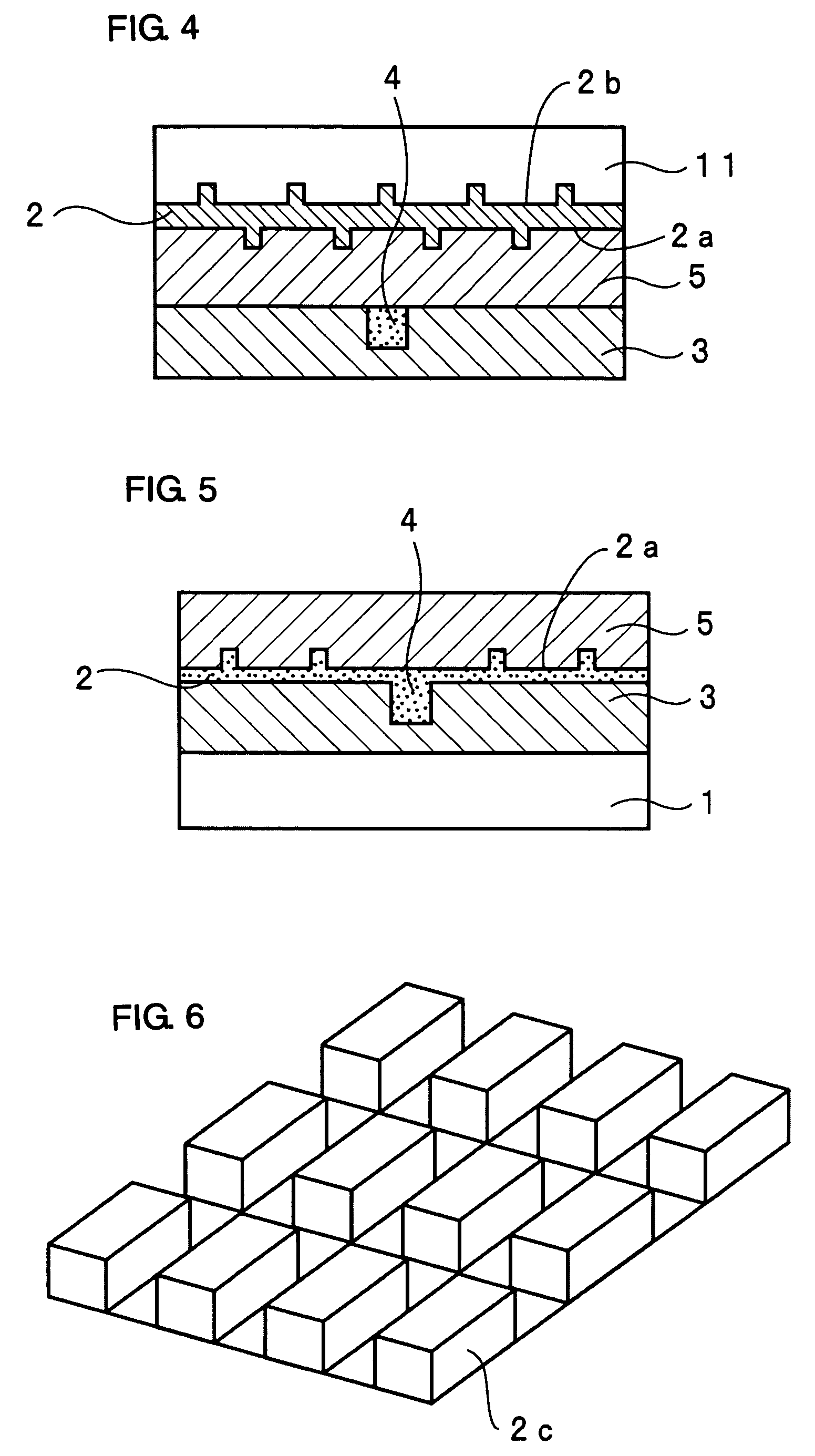
[0130]As a mold 6 for forming recesses and projections on the surface of the ultraviolet control region 2, a mold with the configuration of recesses and projections having the form of stripes, which having a projection portions 2d having the form of stripes as shown in FIG. 7. In addition, the surface roughness Rz of these recesses and projections was 100 nm.
[0131]A four-branch optical waveguide was fabricated for each of the substrates having different thicknesses by following the same procedure as in Example 1 except for using the above-mentioned mold 6. The fabricated four-branch optical waveguide was observed with an optical microscope, and as a result of this, the surface roughness Rz per a length of 250 μm of recesses and projections on an interface of the lower clad layer and the ultraviolet control region was 100 nm.
[0132]And, the insertion losses of the four-branch optical waveguides were measured in the same way as in Example 1. As a result of this, branch-to-branch variat...
PUM
 Abstract
Description
Claims
Application Information
 - R&D
- Intellectual Property
- Life Sciences
- Materials
- Tech Scout
- Unparalleled Data Quality
- Higher Quality Content
- 60% Fewer Hallucinations
Browse by: Latest US Patents, China's latest patents, Technical Efficacy Thesaurus, Application Domain, Technology Topic, Popular Technical Reports.
© 2025 PatSnap. All rights reserved.Legal|Privacy policy|Modern Slavery Act Transparency Statement|Sitemap|About US| Contact US: help@patsnap.com


