
Water current powered motor

a technology of water current and motor, which is applied in the direction of electric generator control, machines/engines, mechanical equipment, etc., can solve the problems of large power projects, insufficient energy supply in usable forms, and insufficient equipment for providing energy in usable forms

Inactive Publication Date: 2009-04-21
HELFRICH JIM C
View PDF22 Cites 31 Cited by
  • Summary
  • Abstract
  • Description
  • Claims
  • Application Information

AI Technical Summary

Benefits of technology

"The present invention is a water powered motor that can extract energy from a water current and convert it into kinetic energy. It consists of a rectangular shape with foldable vanes that receive energy from the water current and use it to power a pump or other equipment such as desalinization machinery. The technical effect of this invention is a more efficient and effective way to harness energy from water currents, which can be useful in various applications such as power generation and desalination."

Problems solved by technology

Many areas of the world are poorly equipped to provide energy in usable forms to help the local population.
Large numbers of people, primarily children are infected with a variety of debilitating and life threatening diseases due to water contamination from bacteria and viruses.
The remoteness and poverty of most of these peoples prevents large power projects from solving the issues.
Continued cost of maintenance prevents the use of simple solutions such as portable generators because there is no money to pay for the fuel to operate them.
The oceans are full of water that has a salinity too high to use for human or animal consumption or for agricultural purposes and the fresh water supply in many of these areas is limited and insufficient to meet the current demands let alone an increase on those demands.
An inexpensive source of power to desalinate the ocean water has not been available.
Often times the problem is complicated by the need to place desalinization equipment miles off shore for best results and the least impact on the environment thus compounding the difficulties of supplying energy to that desalinization equipment.
All of the other solutions except solar contribute to air pollution and often water pollution from the fall out of the carbon based burning or the disposable of the power plats waste.
Other than wood burning by local peoples the cost and maintenance of these power units is significantly higher than most of these peoples in poverty can afford.
Large power plants like hydro electric require hundreds of millions if not billions of dollars of investment and often disrupt the local population and environment often setting off other negative economic issues.
None of these solutions other than solar (which is limited to use during daylight hours) offers a nearly maintenance free source of power that will operate without an energy cost input.

Method used


Image

  • Water current powered motor
  • Water current powered motor
  • Water current powered motor

Examples


Embodiment Construction

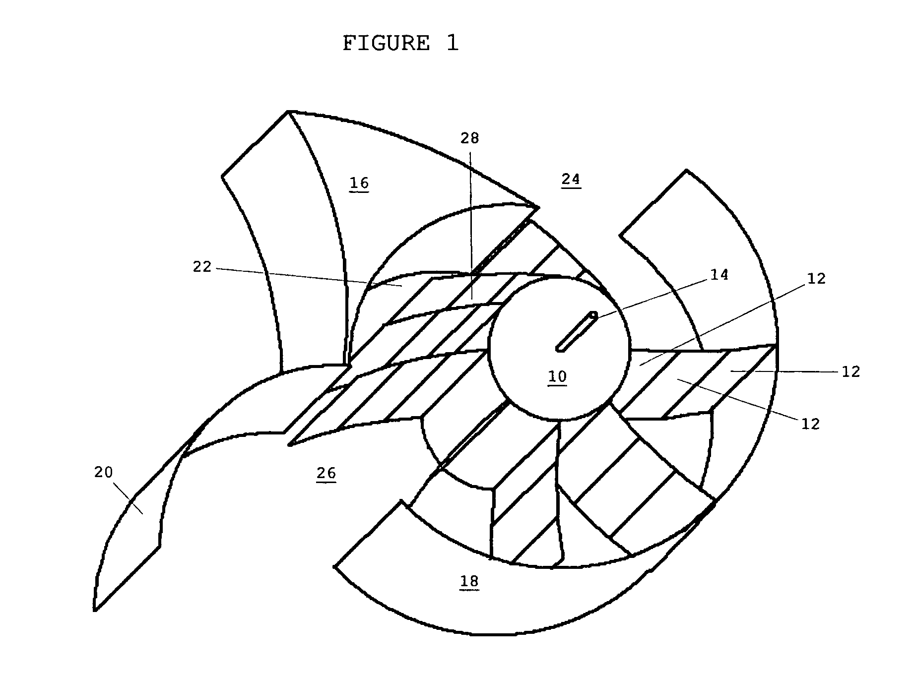
[0027]FIG. 1 is a top perspective view of a power wheel with vanes and diversions.

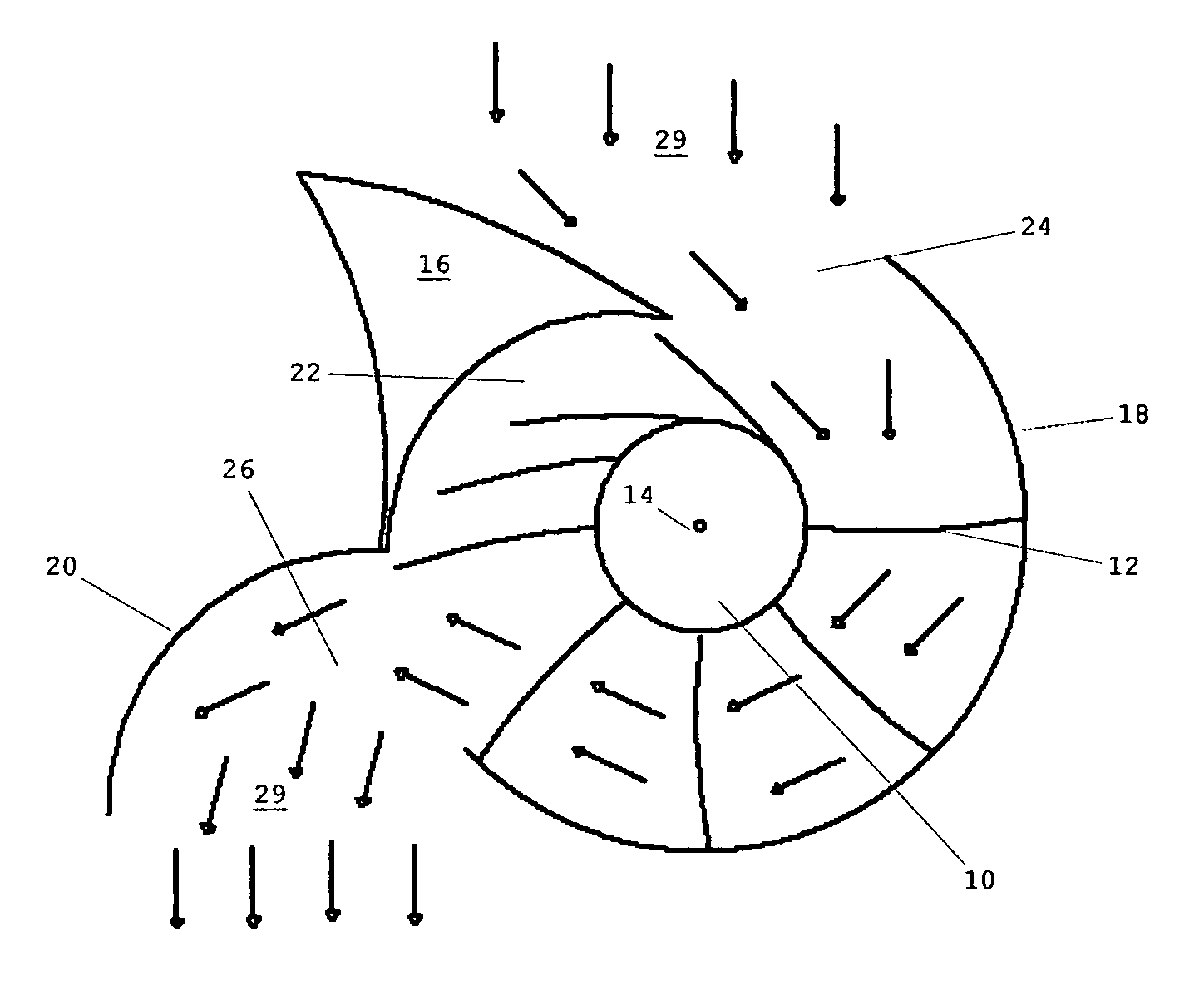
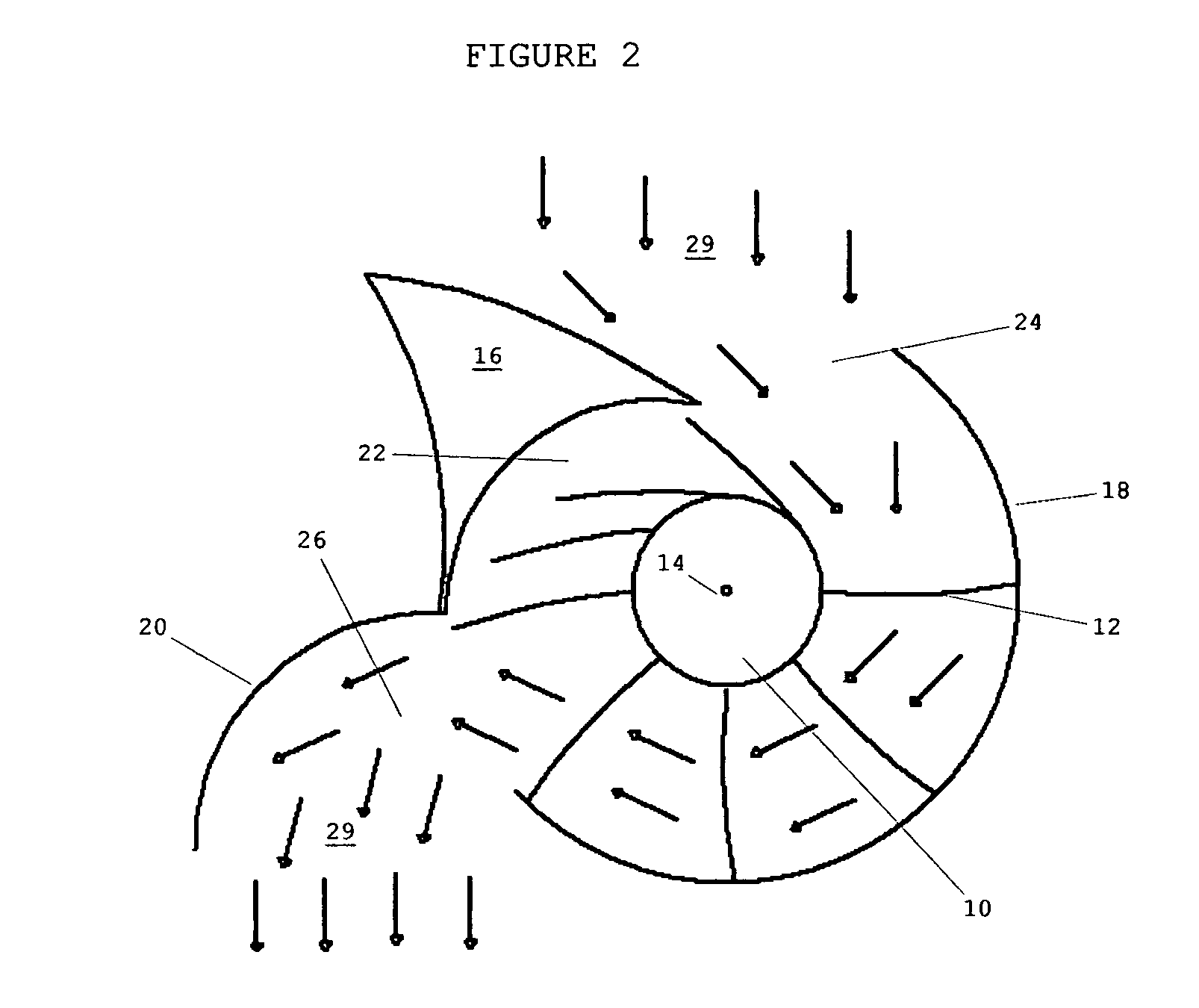
[0028]FIG. 2 is a top partial view of a power wheel with vanes and diversions.

[0029]FIG. 3 is a front elevation view of a vanes showing the section and hinge arrangement.

[0030]FIG. 4 is a rear elevation view of a vane showing sections and stops that prevent over extension of the vanes when under power.

[0031]FIG. 5 is a top elevation view of a vane stop that prevents over extension of the vanes when under power.

[0032]FIG. 6 is a top rear perspective view of the closed unit with all panels in closed and operating positions.

[0033]FIG. 7 is a top rear perspective view of a unit shown with a water vein for directional location so the opening faces into the current.

[0034]FIG. 8 is a bottom rear perspective view of a pivot device that permits the unit to rotate so that the opening is facing the oncoming current for areas where water current 29 direction may change due to tides or tide effects.

[0035]Referring ...


PUM


Abstract

A water powered motor for extracting raw energy from a water current and converting it to kinetic energy. The water powered motor is generally rectangular in shape with a generally round water wheel consisting of foldable vanes. The vanes receive raw energy produced by water current transforming that raw energy into usable energy for powering a pump, electric generator or as a general power source to power other equipment such as desalinization machinery.

Description

RELATED APPLICATIONS[0001]The present application is related to U.S. Pat. No. 7,075,191 B2, issued Jul. 11, 2006, for WIND AND WATER POWER GENERATION DEVICE USING A RAIL SYSTEM, by Davison, included by reference herein.[0002]The present application is related to U.S. Pat. No. 6,930,406 B2, issued Aug. 16, 2005, for TIDE COMPENSATED SWELL POWERED GENERATOR, by Montgomery, included by reference herein.[0003]The present application is related to U.S. Pat. No. 4,872,805, issued Oct. 10, 1989, for WATER POWERED DEVICE, by Horiuchi, included by reference herein.[0004]The present application is related to U.S. Pat. No. 4,737,070, issued Apr. 12, 1988, for WATER POWERED DEVICE, by Horiuchi, included by reference herein.[0005]The present application is related to U.S. Pat. No. 4,686,376, issued Aug. 11, 1987, for TIDE TURBINE, by Retz, included by reference herein.[0006]The present application is related to U.S. Pat. No. 4,176,283, issued Nov. 27, 1979, for WATER POWERED GENERATOR, by McLare...

Claims


Application Information

Patent Timeline
Patent Type & Authority Patents(United States)
IPC IPC(8): F03B1/00F03D3/04
CPCF03B13/264F03B17/065F05B2240/12F05B2240/14F05B2240/40F05B2240/97Y02E10/28Y02E10/30Y02E10/20
Inventor HELFRICH, JIM C.
Owner HELFRICH JIM C
Learn More