
Phase change actuator

a technology of actuator and phase change, which is applied in the direction of relays, machines/engines, mechanical apparatuses, etc., can solve the problem of power required to maintain the switch

Active Publication Date: 2009-04-21
IBM CORP
View PDF10 Cites 63 Cited by
  • Summary
  • Abstract
  • Description
  • Claims
  • Application Information

AI Technical Summary

Problems solved by technology

One problem of these techniques is that power is required to maintain the switch in one of the two states: either open or closed, depending on the design of the switch.

Method used


Image

  • Phase change actuator
  • Phase change actuator
  • Phase change actuator

Examples


Embodiment Construction

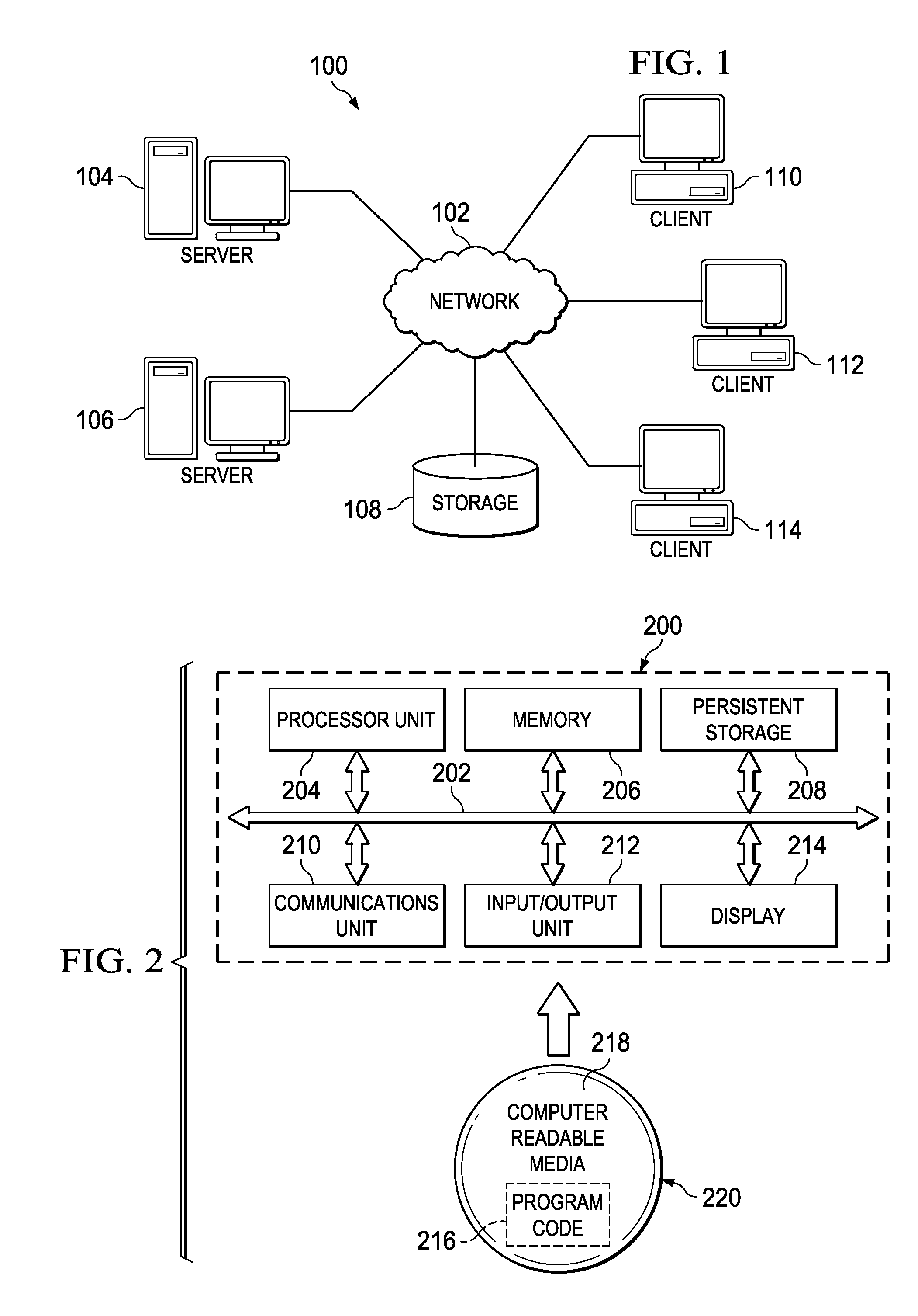
[0010]As will be appreciated by one skilled in the art, the present invention may be embodied as a system, method, or computer program product. Accordingly, the present invention may take the form of an entirely hardware embodiment, an entirely software embodiment (including firmware, resident software, micro-code, etc.) or an embodiment combining software and hardware aspects that may all generally be referred to herein as a “circuit,”“module,” or “system.” Furthermore, the present invention may take the form of a computer program product embodied in any tangible medium of expression having computer usable program code embodied in the medium.

[0011]Any combination of one or more computer usable or computer readable medium(s) may be utilized. The computer-usable or computer-readable medium may be, for example but not limited to, an electronic, magnetic, optical, electromagnetic, infrared, or semiconductor system, apparatus, device, or propagation medium. More specific examples (a non...


PUM


Abstract

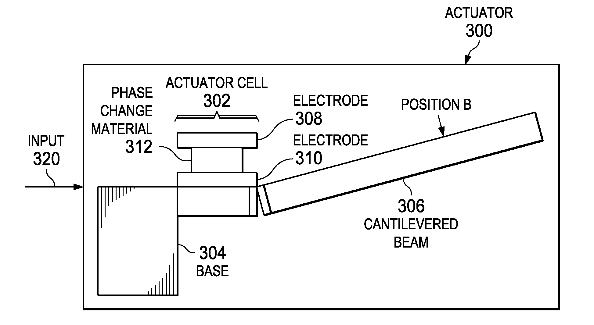
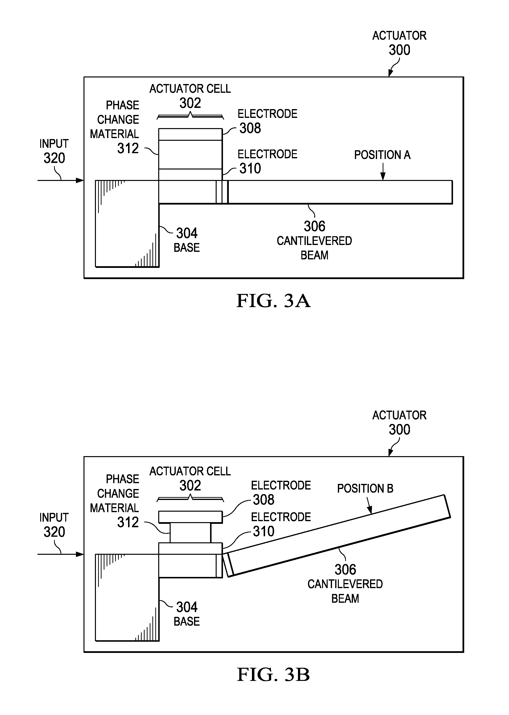
An actuator is provided. The actuator comprises a base portion, a cantilever beam connected to the base portion, and an actuator cell adjacent to the cantilever beam. The actuator cell comprises a first metal electrode positioned on the cantilevered beam, a second metal electrode positioned near the first metal electrode, and phase change material between the first and second metal electrodes, wherein the phase change material connects the first metal electrode to the second metal electrode, wherein applying a burst of energy to the phase change material causes the phase change material to change between an amorphous state and a crystalline state, causing the cantilevered beam to move between a first position and a target position, wherein the cantilevered beam remains at the target position upon removal of the energy.

Description

BACKGROUND OF THE INVENTION[0001]1. Field of the Invention[0002]The present invention relates generally to actuators and more specifically to actuating actuators using phase change material.[0003]2. Description of the Related Art[0004]Micro electromechanical systems (MEMS) based switches potentially have a very low resistance, a large on / off resistance ratio, and relatively small form factors, making them good candidates for radio frequency switching applications, such as switching antennas in a mobile phone for operation in a different frequency band, or for power management applications in multi-core microprocessors, such as switching unused cores off. The basic principle of a MEMS switch is analogous to a macroscopic relay, i.e. a spring loaded switch, typically a cantilever beam, is actuated up or down to open or close a metallic contact. In order to make a good contact, relatively large actuation forces are needed. To date, most MEMS switches use either piezo-electric or electr...

Claims


Application Information

Patent Timeline
Patent Type & Authority Patents(United States)
IPC IPC(8): H01H37/46F03G7/06
CPCB81B3/0072H01H61/01B81B2201/07B81B2203/0118B81C2201/0167H01H2061/006
Inventor LANTZ, MARK ALFRED
Owner IBM CORP
Learn More