Projection-based head-mounted display with eye-tracking capabilities

Active Publication Date: 2009-04-21
UNIV OF CENT FLORIDA
View PDF7 Cites 355 Cited by
  • Summary
  • Abstract
  • Description
  • Claims
  • Application Information

AI Technical Summary

Benefits of technology

[0014]A second embodiment provides a method for providing eye-tracking in a projection-based head-mounted display. The method includes providing an infrared light from a light source for illuminating a pupil of a user's eye, using an optical device to create a head-mounted display optical path and an eye-tracking optical path, wherein the head-mounted display and the eye-tracking optical paths are shared to reduce weight of the projection based head-mounted display, recording a bright pupil image and a dark pupil image created by the infrared light using a camera, and extracting an eye movement data from the bright pupil image and the dark pupil image using a pupil/glint method. The eye movement extracting comprises the steps of creating plural glints in an eye of a user using the infrared light and calculating a centroid of the shape formed by the plural glints from the bright pupil image and the dark pupil image for tracking the eye movement. The method further comprises using a first and a second infrared light source having a first and a second infrared light output, respectively, positioning the first infrared light source to provide a first infrared light on-axis with a point of vi

Problems solved by technology

Issues associated with an eyepiece-based system include lack of compactness and large distortion for wide field of view designs, because the aperture stop of the system is located outside of the lens which has promoted other designs such as the head-mounted projection displays.
While head-mounted display technologies have undergone significant developments in the last decade, they have

Method used


Image

  • Projection-based head-mounted display with eye-tracking capabilities
  • Projection-based head-mounted display with eye-tracking capabilities
  • Projection-based head-mounted display with eye-tracking capabilities

Examples


Embodiment Construction

[0032]Before explaining the disclosed embodiments of the present invention in detail it is to be understood that the invention is not limited in its application to the details of the particular arrangements shown since the invention is capable of other embodiments. Also, the terminology used herein is for the purpose of description and not of limitation.

[0033]The following is a list of the reference numbers used in the drawings and the detailed description to identify components:

[0034]

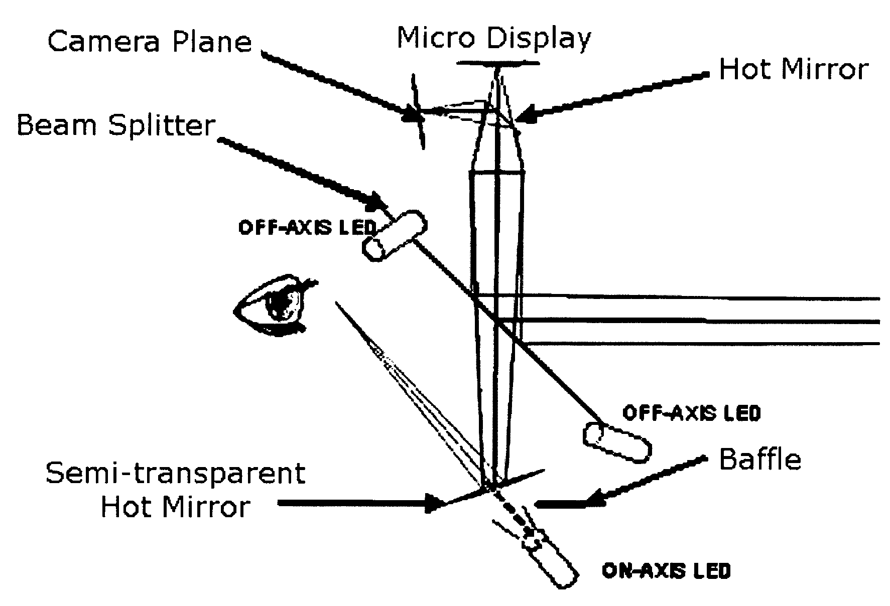
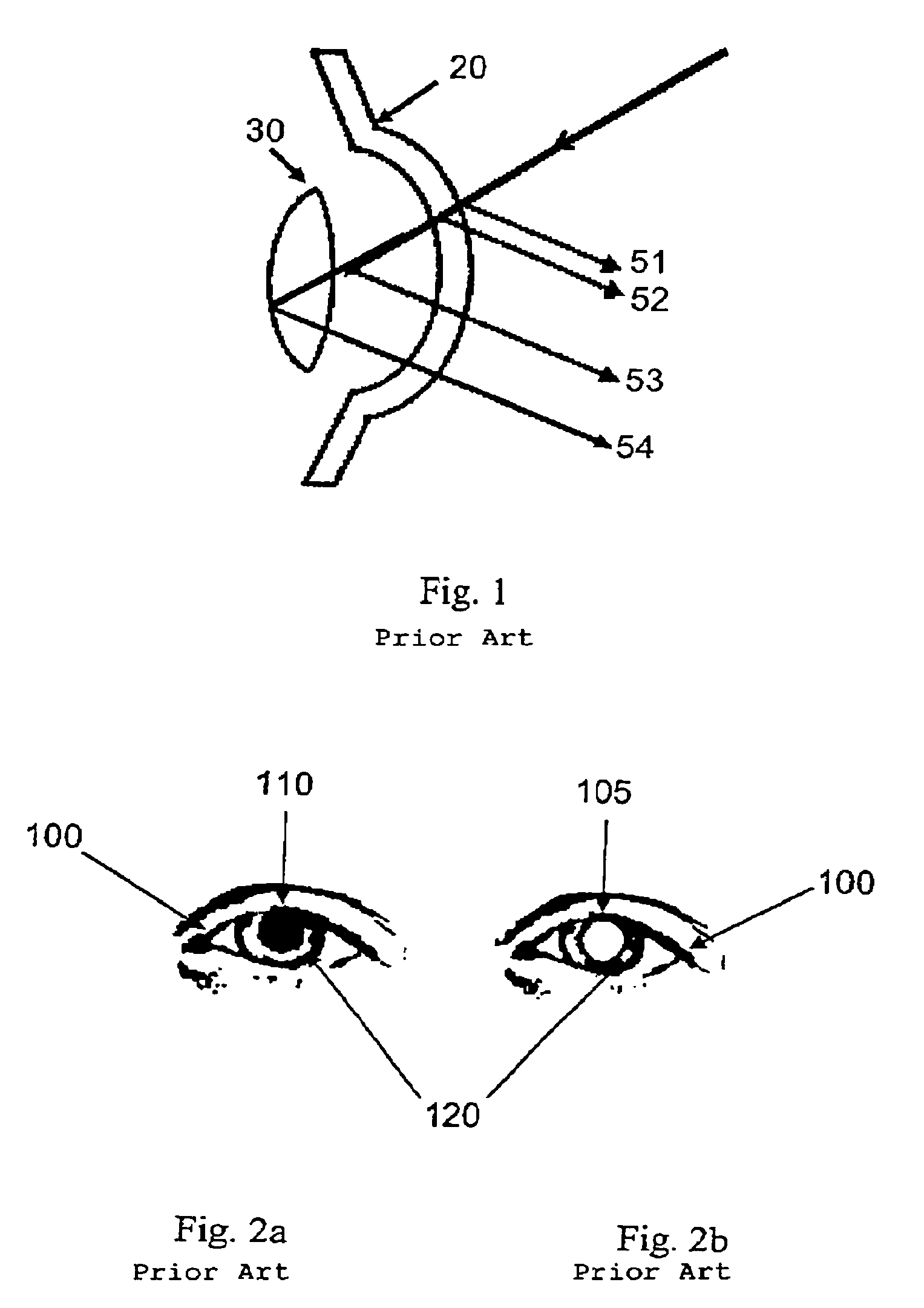
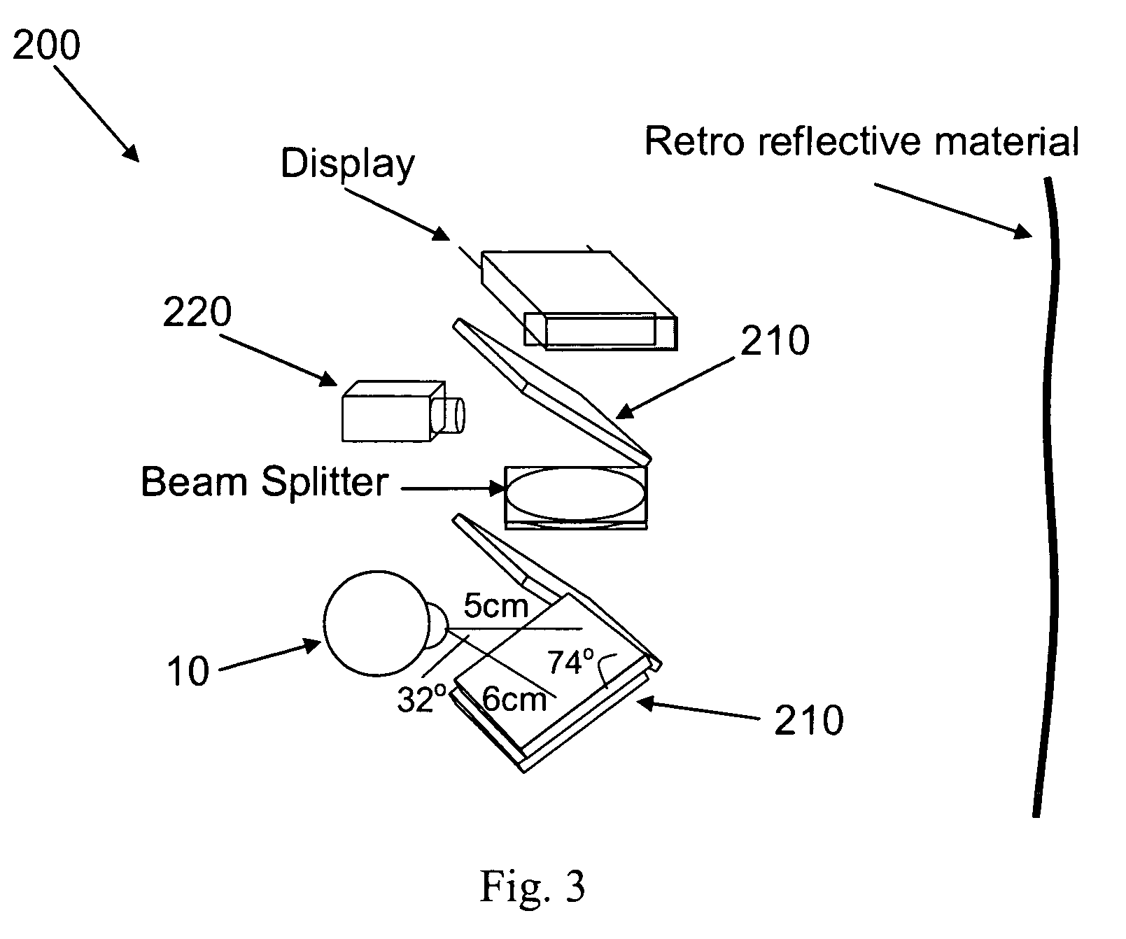
10eye51first reflection20cornea52-54reflections30lens100eye105light pupil300top mirror110dark pupil305on-axis LED120glint310bottom mirror200system315off-axis LED210mirror320beam splitter220camera330camera plane340micro display

[0035]Several ways of tracking the eye-gaze direction exist. These methods can be divided into three main categories as described in Andrew T. Duchowski, Eye Tracking Methodology—Theory and Practice, Springer (2003). The first one is the contact lens method in which the user is re...


PUM


Abstract

Methods, systems, apparatus and devices for the lens design of an HMPD with eye-tracking capabilities. The integration uses a low-level optical configuration in order to achieve a compact, comfortable, easy-to-use system. The optical system is further designed and optimized for sharing of the optical path between the HMD and the Eye-Tracker with minimal performance loss for both tasks.

Description

[0001]This application claims the benefit of priority to U.S. Provisional Patent Application No. 60 / 750,204 filed on Dec. 14, 2005.FIELD OF THE INVENTION[0002]This invention relates to head mounted displays and, in particular, to methods, systems, apparatus and devices for projection based head mounted displays with eye tracking capabilities.BACKGROUND AND PRIOR ART[0003]Head mounted displays are widely used for three-dimensional (3D) visualizations tasks such as simulators, surgery planning, medical training, and engineering design. Traditionally the head mounted display technology has been based on eyepiece optics. Issues associated with an eyepiece-based system include lack of compactness and large distortion for wide field of view designs, because the aperture stop of the system is located outside of the lens which has promoted other designs such as the head-mounted projection displays.[0004]Head mounted projection display is a technology that is positioned at the boundary betwe...

Claims


Application Information

Patent Timeline
IPC IPC(8): G02B27/12G09G5/00
CPCG02B27/0093G02B27/017G06F3/013G02B2027/0138G02B2027/0187
Inventor CURATU, COSTIN E.ROLLAND, JANNICK P.
Owner UNIV OF CENT FLORIDA
Why Eureka
Try Eureka