
Method and apparatus for wireless routing on a plurality of different wireless channels

a wireless communication and wireless channel technology, applied in the direction of data switching networks, wireless commuication services, frequency-division multiplex, etc., can solve the problems of degrading overall qos, affecting the efficiency of data transmission, and using the current state of the art, so as to increase improve the qos of data transmission, and improve the effect of variation

Inactive Publication Date: 2009-04-21
MICROSOFT TECH LICENSING LLC
View PDF13 Cites 48 Cited by
  • Summary
  • Abstract
  • Description
  • Claims
  • Application Information

AI Technical Summary

Benefits of technology

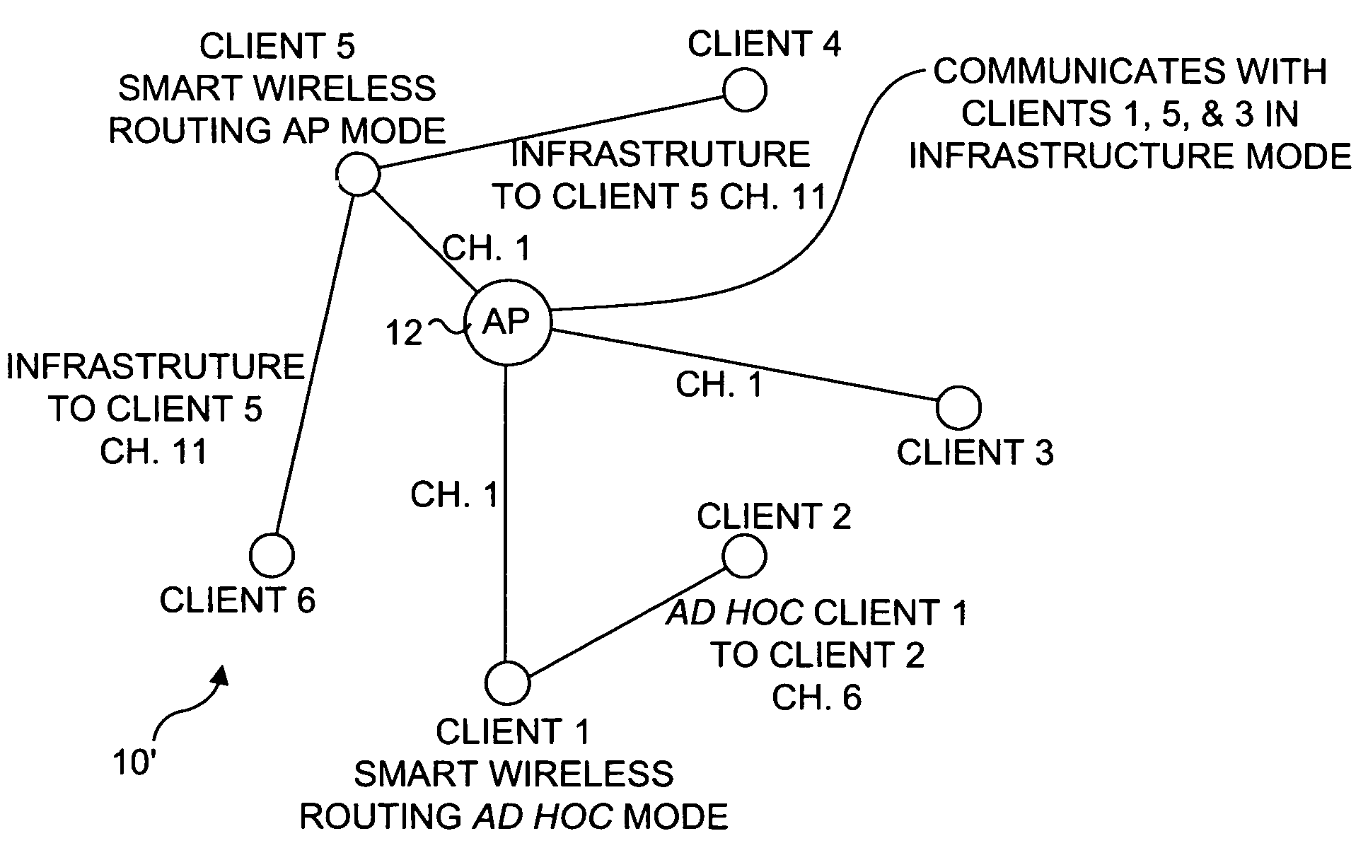
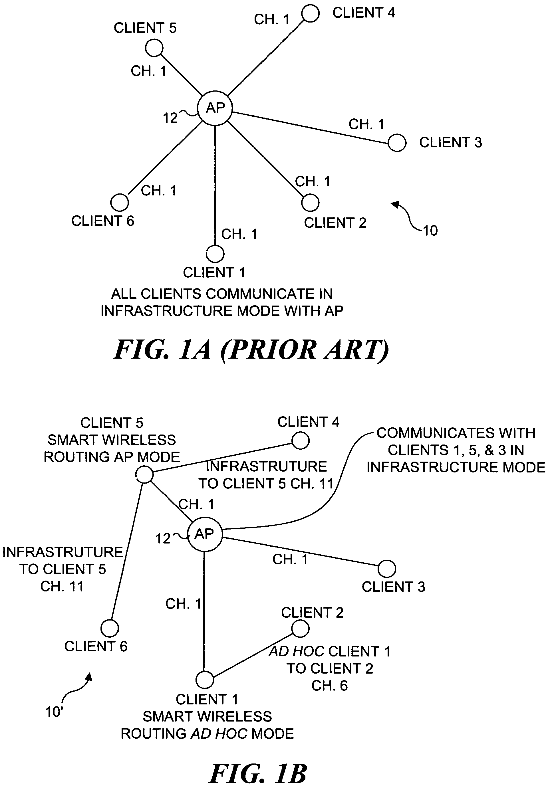
[0014]In consideration of the inefficiency that exists in current wireless networks with wireless devices having different data rate capabilities and the need to transfer different types of data, the present invention makes more effective use of the available bandwidth by enabling the wireless devices to connect directly to each other on an independent wireless network, either temporarily or permanently, for the purposes of increased QoS in data transfers. The present invention creates more efficient variations than the typical star-topology with a wireless AP at the center and its wireless clients all communicating through the AP at the hub. Further, the present invention provides ways to create efficiencies without enhancing every element in the system, so that the wireless network can continue to operate with current state of the art devices. The devices are allowed to directly connect to each other in either ad hoc or infrastructure modes, as most appropriate, and also devices of like data rate are enabled to communicate, as appropriate for transferring specific types of data. It is not necessary for a user to manually selectively operate a wireless device in a particular mode when communicating with a selected other wireless device, because the present invention automatically facilitates the communication protocol between two wireless devices when needed.
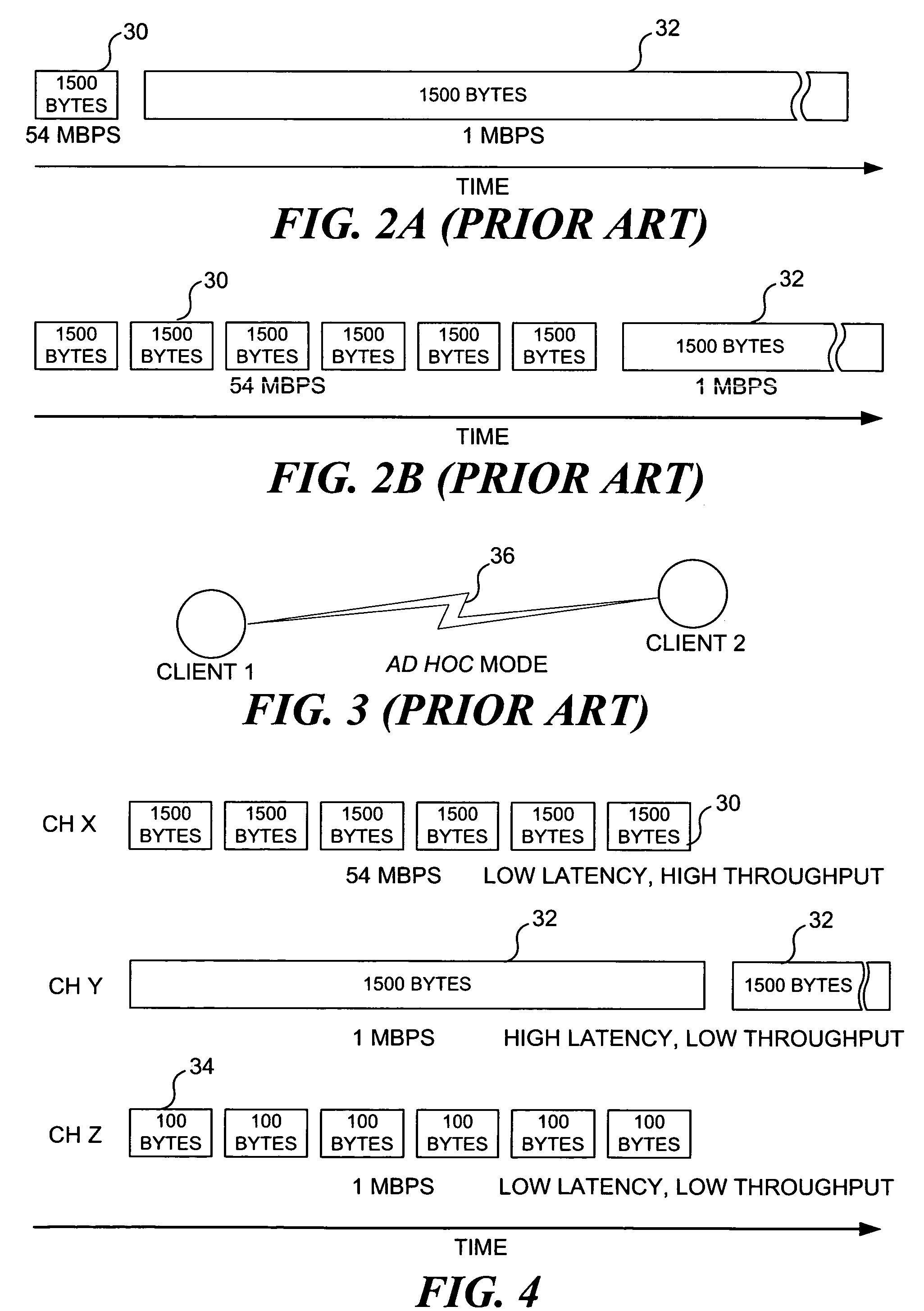
[0025]Yet another aspect of the present invention is directed to a method for efficiently communicating data over a wireless network. For data being communicated between wireless devices, the method determines at least one of a type of data being communicated between specific wireless devices, a size of data packet to be communicated between specific wireless devices, a frequency band with which the data will be communicated, and a nominal data rate with which the data will be communicated. The wireless devices communicating different types of data are automatically caused to communicate over different wireless channels, so that a first wireless channel is used for communication of a first type of data between a first set of wireless devices, and a second wireless channel is used for communication of a second type of data between a second set of wireless devices. In addition, the method includes automatically enabling communication dynamically between selected pairs of wireless devices that are communicating the same type of data, and automatically enabling communication dynamically back to the original infrastructure mode for wireless devices that are communicating data from an external network through a central AP wireless device.

Problems solved by technology

As was noted in the discussion of FIG. 1A, there are disadvantages in using the current state of the art when clients 1 and 2 need to exchange data.
First if both remain associated to the AP, the effective bandwidth is halved because the data must travel on two “hops.” Second, if other wireless clients such as clients 3, 4, 5, or 6 are communicating at the same time that wireless clients 1 and 2 are in communication, there is competition for bandwidth and overall QoS is degraded.

Method used


Image

  • Method and apparatus for wireless routing on a plurality of different wireless channels
  • Method and apparatus for wireless routing on a plurality of different wireless channels
  • Method and apparatus for wireless routing on a plurality of different wireless channels

Examples


Embodiment Construction

[0045]As explained above under the Background of the Invention section, one of the problems of the existing approach used for conveying data in a wireless network arises because wireless devices that are capable of communicating only at relatively slower rates, such as devices meeting the IEEE 802.11b standard, slow the communication of data over the entire network in regard to a base station or wireless AP that would otherwise be able to communicate with faster wireless devices meeting either the IEEE 802.11a or IEEE 802.11g standards. Furthermore, although the slower data rate may be entirely acceptable for certain types of data such as html data for web pages, which is often more limited by the download speed of a broadband connection to the Internet, other types of data such as video data packets require a higher data rate for acceptable performance on a wireless network. Therefore, one important aspect of the present invention is its allocation of different types of data transf...


PUM


Abstract

To provide enhanced quality of service (QoS) communication capability, a wireless network is implemented in which different channels are used for conveying different types of data and in which wireless devices are selectively operated in either an infrastructure or ad hoc mode automatically selected to make best use of the available communication bandwidth. For example, a wireless device for a computer can be operated selectively as a client wireless device that is in communication with a legacy access point in an infrastructure mode on one channel, while using one or more different channels to communicate selectively in either ad hoc mode or infrastructure mode with client devices. To make efficient use of wireless devices, IEEE 802.11a or 802.11g wireless devices are used for communicating audio / video data on one channel, while an IEEE 802.11b wireless device is used on a different channel for communicating web page data.

Description

RELATED APPLICATIONS[0001]This application is a continuation-in-part of prior U.S. patent applications, Ser. No. 10 / 428,218, filed May 2, 2003, Ser. No. 09 / 953,980, filed Sep. 17, 2001 now U.S. Pat. No. 7,248,570, and Ser. No. 09 / 954,087, filed Sep. 17, 2001 now U.S. Pat. No. 7,194,263, the benefit of the filing dates of which is hereby claimed under 35 U.S.C. § 120.FIELD OF THE INVENTION[0002]The present invention generally relates to the routing of wireless communications through a client on a wireless network, and more specifically, pertains to a method and a system for employing a client device to communicate with a plurality of other wireless devices on different channels, to route communications from one wireless AP to another wireless device, or to enhance communications with the other wireless devices.BACKGROUND OF THE INVENTION[0003]Wireless communications have become increasingly common for networking client devices together in offices and homes. An example of a simple con...

Claims


Application Information

Patent Timeline
Patent Type & Authority Patents(United States)
IPC IPC(8): H04W4/00H04L12/26H04W40/00H04W88/04
CPCH04W40/00H04L45/306H04W88/04
Inventor GIAIMO, EDWARD C.PENNOCK, JOHN P.BAHL, PARAMVIRBAHL, PRADEEP
Owner MICROSOFT TECH LICENSING LLC
Learn More