Railcar truck bolster side bearing mounting pad milling machine and method

a technology for mounting pads and railcars, which is applied in the field of milling machines, can solve the problems of inability to accurately fit the side bearing assembly between the top of the bolster and the underside of the railcar, unsatisfactory impact of the railcar with the side bearing assembly, and the inability of known machines for milling railcar bolster side bearing mounting pads to continually provide precise and repeatability, so as to achieve more precise and repeatable locating

Inactive Publication Date: 2009-04-28
COLUMBUS STEEL CASTINGS
View PDF9 Cites 15 Cited by
  • Summary
  • Abstract
  • Description
  • Claims
  • Application Information

AI Technical Summary

Benefits of technology

[0009]A side bearing milling machine of the present invention incorporates a highly rigid, moveable saddle and fixture assembly, that allows the bolster to be supported from its underside. More specifically, the bolster is supported in an upright position within the fixture by the spring seats located near each end of the bolster. Once properly positioned within the fixture, the bolster is then securely clamped to prevent its movement. Downward clamping force presses the spring seats against the underlying fixture, thereby ensuring the accurate and repeated positioning of the bolster and the side bearing mounting pads.
[0011]A side bearing milling machine of the present invention allows for more precise and repeatable locating of a railcar truck bolster than has been capable with previously known machines. Supporting the bolster from underneath prevents gravity and / or the downward forces exerted by the milling heads to displace the bolster and side bearing mounting pads during the machining process. Further, by eliminating the need to raise the bolster into proper cutting position, the wear problem associated with such a design has been obviated. Consequently, a side bearing milling machine of the present invention allows the side bearing mounting pads of a railcar truck bolster to be repeatedly machined to a precise tolerance, without requiring the frequent replacement of positioning components or the adjustment of bolster position that has typically accompanied the use of known machines.

Problems solved by technology

For example, if an excessive amount of material is removed from a side bearing mounting pad, there may be a gap between the side bearing assembly affixed thereto and the underside of the railcar—which may lead to an undesirable impacting of the railcar with the side bearing assembly when the railcar negotiates curves or encounters a rough section of track.
In contrast, the removal of an inadequate amount of material from a side bearing mounting pad may make it difficult or impossible to properly fit the side bearing assembly between the top of the bolster and the underside of the railcar.
Known machines for milling railcar bolster side bearing mounting pads have proven incapable of continually providing precise and repeatable results.
Rather, wear problems inherent to the design of these known machines eventually causes the side bearing mounting pads to be machined out of tolerance—unless certain components of the machines are frequently replaced, or the bolsters are shimmed or otherwise manipulated into proper position when in the machines.
This technique is problematic for multiple reasons.
First, both gravity and the downward pressure exerted by the milling heads against the side bearing mounting pads act against the lifting mechanism responsible for raising the bolster.
Thus, it is difficult to maintain the bolster in the exact position necessary to allow for milling the pads precisely to the required depth.
Second, repeated impact between the top surface of the bolster and the overlying hard stops produces excessive wearing of the hard stops.
Further, the hard stops may experience dissimilar amounts of wear, thereby allowing the side bearing mounting pads to be milled to different heights.

Method used


Image

  • Railcar truck bolster side bearing mounting pad milling machine and method
  • Railcar truck bolster side bearing mounting pad milling machine and method
  • Railcar truck bolster side bearing mounting pad milling machine and method

Examples


Embodiment Construction

)

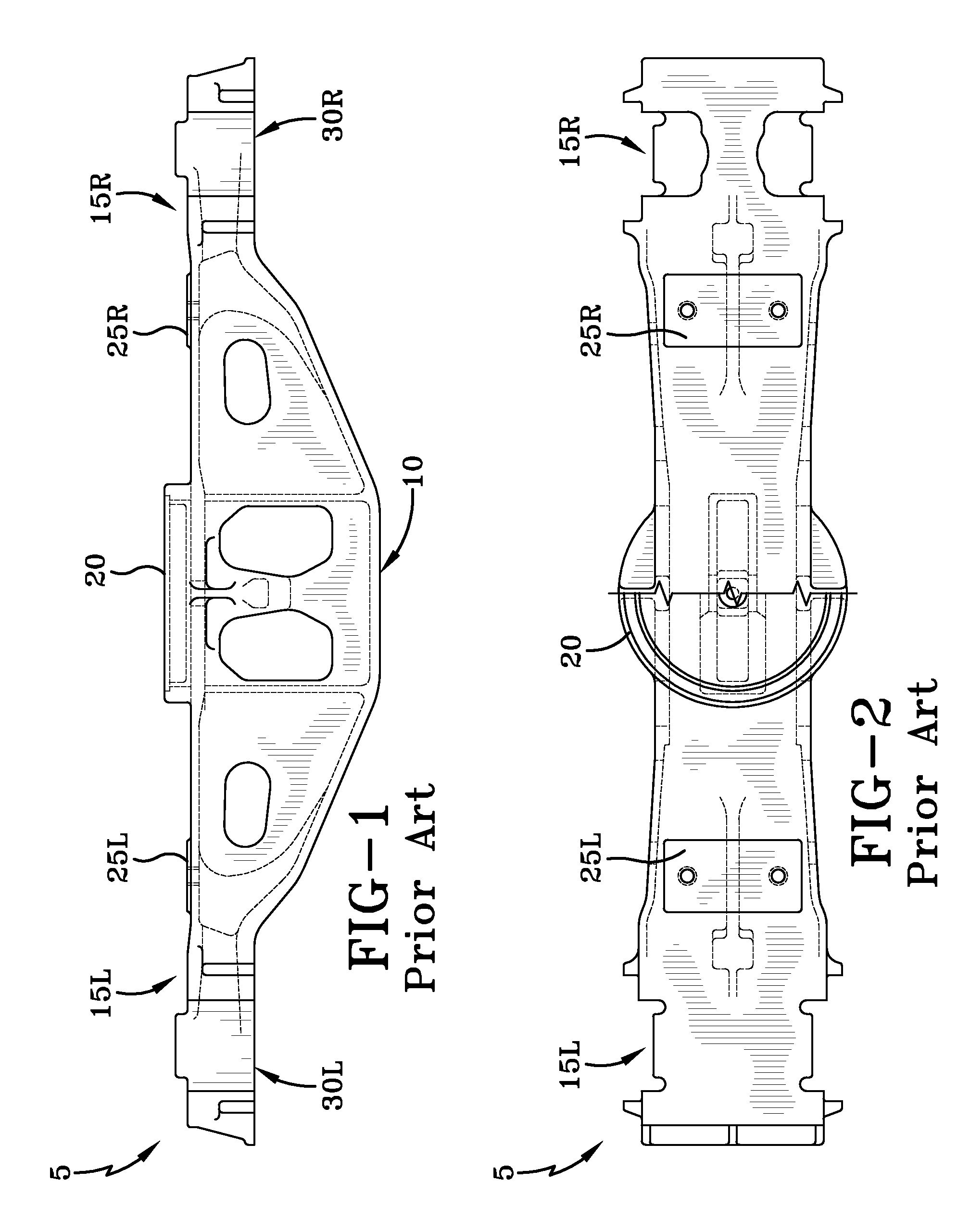
[0020]A typical railcar bolster is illustrated in FIGS. 1-2. As can be seen, the bolster 5 is basically an elongated member having a widened center portion 10 from which extends a pair of bolster arms 15L, 15R. In operation, the center portion 10 sits beneath and substantially along the midline of a railcar. A connecting element 20 is provided to facilitate attachment of the railcar to the bolster 5.

[0021]A top surface of each bolster arm 15L, 15R, can be seen to include a side bearing mounting pad 25L, 25R. In the embodiment of the bolster 5 shown in FIGS. 1-2, the side bearing mounting pads 25L, 25R are located approximately midway between the center portion 10 and the distal end of the bolster arms 15L, 15R, although this position may vary. A spring seat 30L, 30R lies along a bottom surface of each bolster arm 15L, 15R, and near the distal end thereof. The spring seats 30L, 30R abut the tops of the springs that reside between each end of the bolster arm 5 and the side frames (no...


PUM

PropertyMeasurementUnit
diameteraaaaaaaaaa
movementaaaaaaaaaa
areaaaaaaaaaaa

Abstract

A railcar truck bolster side bearing mounting pad milling machine and method. A milling machine of the present invention includes a pair of milling heads and associated cutters suspended from an overhead frame member. A sliding saddle unit is provided for transporting the bolster into and out of a work envelope of the milling machine. At least one fixturing assembly is attached to the sliding saddle unit to support and fix the position of the bolster in three directions. The bolster is rigidly supported from its underside, thereby eliminating the risk that the bolster may move downward during machining. Since the vertical position of the bolster when presented to the cutters is fixed, thereby the need to raise the bolster into a working position is also eliminated.

Description

BACKGROUND OF THE INVENTION[0001]The present invention is directed to a milling machine for cutting the side bearing pads of a railcar truck bolster. More particularly, the present invention is directed to a milling machine that is capable of precisely and repeatedly machining the side bearing mounting pads of a cast railcar truck bolster.[0002]A railcar rides on and is supported by what is known as a railcar truck. Commonly, there are two trucks per railcar. Each truck generally includes two elongated and transversely spaced side frames that rest on corresponding wheel sets provided to engage a set of train tracks. An elongated truck bolster (bolster) typically extends substantially perpendicularly between, and is connected to, the pair of side frames. Normally, the bolster is supported on the side frames by a number of springs that serve to provide the railcar and its cargo with a cushioned ride. The springs reside between the side frames and a spring seat area on the underside of...

Claims


Application Information

Patent Timeline
Patent Type & Authority Patents(United States)
IPC IPC(8): B23C3/00
CPCB25B5/163B23C3/00B25B5/00Y10T409/307728Y10T29/49995Y10T409/308288Y10T409/303808Y10T409/305544Y10T409/307448Y10T409/307168Y10T409/308736
Inventor COLEMAN, RONALDMILLIGAN, BRUCE
Owner COLUMBUS STEEL CASTINGS
Why Eureka
Try Eureka