Method of producing wheel and the wheel

a production method and wheel technology, applied in the field of producing wheels, can solve the problems of high cost of large-scale press devices, achieve the effects of reducing the time required for changing, preventing material flow or migration, and facilitating the change of molds

Inactive Publication Date: 2009-04-28
WASHI KOSAN
View PDF13 Cites 14 Cited by
  • Summary
  • Abstract
  • Description
  • Claims
  • Application Information

AI Technical Summary

Benefits of technology

[0022]When to form the holes that make a disk-part pattern, two or three varieties of the molds are used and changing of the mold is facilitated by hanging the molds from rails that are arranged on an end of the press device on its pressing side, as to decrease time required for changing the upper, molds. Detail of the press device will be described in the embodiment. Ridges along the recesses or the through holes on the lower mold at places matching the sharp-angled ridges of the projections on the upper mold are shaped as the sharp-angled ridges as in same manner, for cutting the material.
[0029]Providing the holes on the wheel is effective in decreasing weight of the wheel though extent of the decreasing depends on size of the holes; and the aperture ratio of 25% may be rather small. Mass corresponding the waste holes is not included in the mass of the completed product thus required amount of the lightweight metal is increased, however, metal fragments resulted from punching may be reused.

Problems solved by technology

Such a large-scale press device is expensive and requires an accordingly sizable place for installing the device.

Method used


Image

  • Method of producing wheel and the wheel
  • Method of producing wheel and the wheel
  • Method of producing wheel and the wheel

Examples


embodiment 1

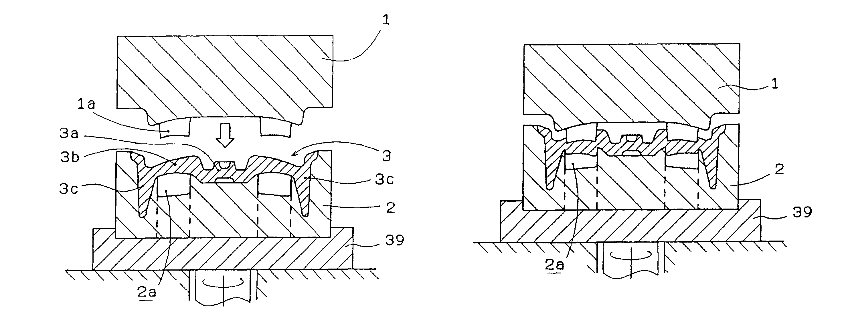
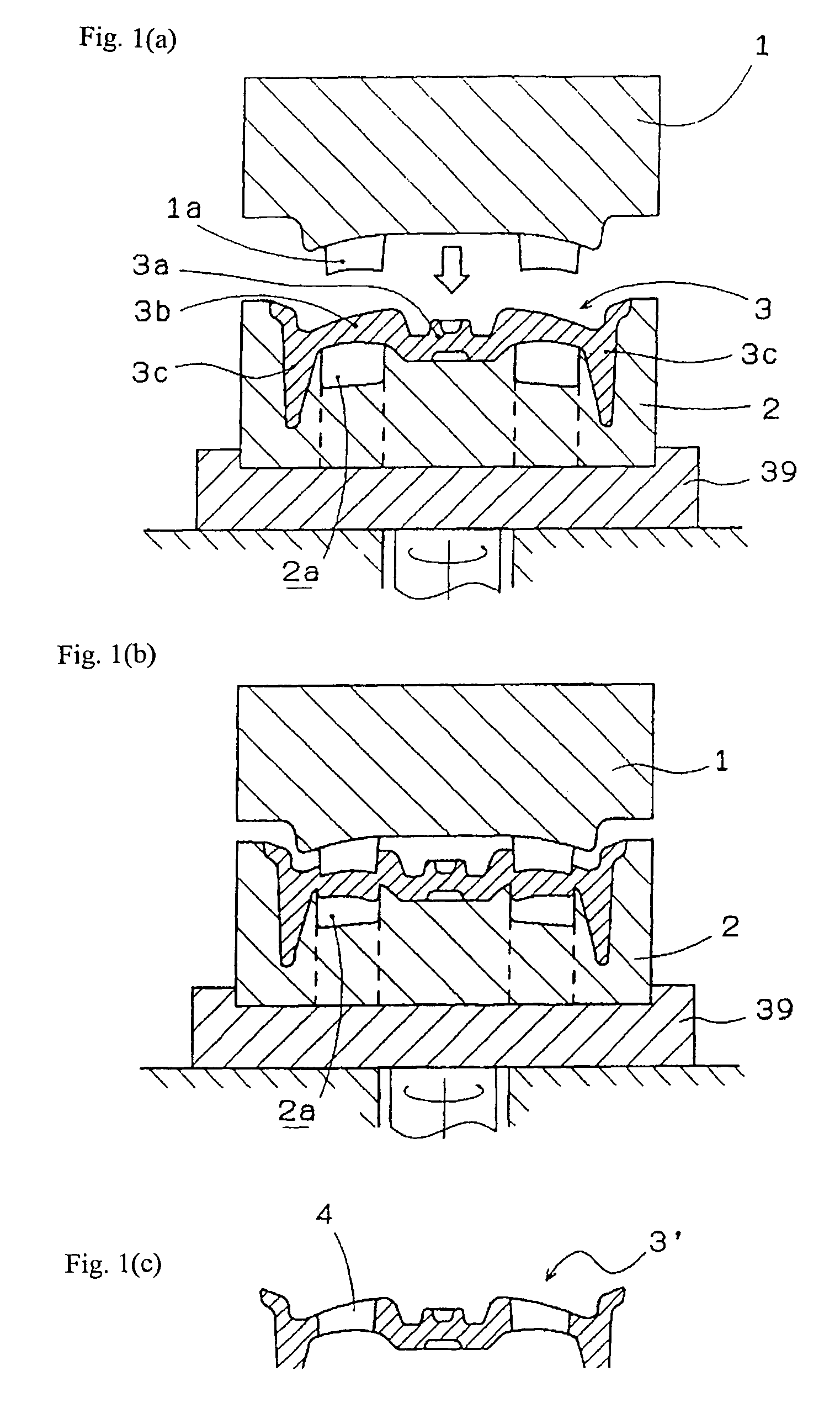
[0043]FIG. 1(a) is a vertical sectional view schematically showing an intermediate product and molds, which are used for the invention-wise rotational forging. Numeral 1 designates the upper mold that moves upward and downward in vertical direction. Numeral 2 designates the lower mold that is mounted on a bed 39 rotated by not-illustrated driving device and controlled as to repeat rotation by certain angle and subsequent stopping. Numeral 3 designates intermediate product formed of lightweight alloy of; aluminum, magnesium or the like. The intermediate product has a to-be-hub boss 3a, a discoid 3b around the boss, and a cylindrical thick wall 3c around the discoid for forming a rim. Though not illustrated, the intermediate product and the molds are heated by burners at around the molds so as to be maintained at a temperature range of 420 through 450° C., at which the intermediate product easily undergo a plastic deformation. The upper mold 1 having projections 1a moves downward by a...

embodiment 2

[0057]This embodiment is made by taking account the fact that the waste holes alleviate extent of thrust force of the upper mold, whereas it has been mentioned that the waste holes 13a and 13b facilitate the “flow” of the metal in an explanation with respect to the FIG. 5.

[0058]In this embodiment, firstly, a pre-wheel 18 shown in FIG. 8(a) is formed by the portion-by-portion-wise forging from a billet formed of lightweight metal. The portion-by-portion-wise forging here is made in a manner that; the lower mold is rotated by a predetermined angle and then stopped; subsequently, the upper mold moves down and presses a portion of the billet; and such process is repeated, as to expand the billet.

[0059]The pre-wheel 18 is disk-shaped and has a pre-rim 19 on its periphery and a pre-disk 20 on center part. Subsequently, as shown in FIG. 8(b), waste holes 13a and 13b are punched out as to form a punched pre-wheel 18a.

[0060]FIG. 8(c) is a sectional view for indicating outline of the forging...


PUM

PropertyMeasurementUnit
sharper angleaaaaaaaaaa
angleaaaaaaaaaa
diameteraaaaaaaaaa

Abstract

A method of producing a light alloy wheel with a forging technique, aiming for producing the wheel having a large-diameter disk by use of a small-scale press device, comprising: heating an intermediate product that is formed by casting or forging and has a discoid and a cylindrical thick wall, which are to respectively become disk and rim at completion, to a plasticity temperature; then, rotating the intermediate product with stopping of the rotating at interval of a predetermined angle; pressing at least a portion of the to-be disk part by molds at time of said stopping, as to push out metal into recesses on the lower mold and to thereby form holes; repeating of such rotating, stopping and pressing as to give a pattern on whole of the to-be disk part; and further press processing and finish processing on the to-be disk and the to-be rim parts.

Description

FIELD OF THE INVENTION[0001]This invention relates to a method of producing wheel formed of lightweight metal for a vehicle as well as such wheel.BACKGROUND OF THE INVENTION[0002]The wheels formed of lightweight metal that are preferably used in passenger automobiles greatly contribute for decreasing load underneath the springs and for improving maneuverability and fuel efficiency or mileage. Such wheels are produced by casting or forging as to provide ones having excellent ornamental appearances. In response to quest for wheels more lightweight and more excellent in the ornamental appearances, the lightweight metal wheels allegedly have a share exceeding 60% in wheels for the passenger automobiles. With increase of speed capacity of the passenger automobile, there is required enlargement of brake mechanism and of the wheel; thereby, diameter of the wheels increases year by year and may well soon exceed 17 inch in nowadays trend.[0003]In producing the lightweight metal wheels, alumi...

Claims


Application Information

Patent Timeline
Patent Type & Authority Patents(United States)
IPC IPC(8): B21D22/00B21B15/00B23P17/00B21D28/00B21B27/06B21K1/32B22C9/22B60B3/06
CPCB21J5/008B21K1/32B60B3/06B22C9/22Y10T29/49504B21J1/06B21K1/38B22C9/28
Inventor ONO, KOTARO
Owner WASHI KOSAN
Why Eureka
Try Eureka