Internal combustion engine and outboard motor provided with the same

a technology of internal combustion engine and outboard motor, which is applied in the direction of combustion air/fuel air treatment, machines/engines, special-purpose vessels, etc., can solve the problems of engine cover vibrating, noise generation, and inability to achieve the effect of reducing intake nois

Active Publication Date: 2009-04-28
HONDA MOTOR CO LTD
View PDF16 Cites 5 Cited by
  • Summary
  • Abstract
  • Description
  • Claims
  • Application Information

AI Technical Summary

Benefits of technology

[0011]According to the present invention, water contained in the combustion air taken in through the intake air inlet into the intake air passage is separated from the combustion air by centrifugal force while the combustion air flows through the reversing passage. Since the combustion air that has flowed through the reversing passage flows through the up passage to the level higher than that of the uppermost one of the intake air outlets, and then flows down through the second down passage and flows through the intake air outlets into the combustion chamber, water can be surely separated from the combustion air while the combustion air is flowing up through the up passage as compared with a state where the combustion air flows out through intake air outlets formed in an intermediate part of the up passage below the upper end of the up passage. Thus the water trapping effect can be improved. When the intake air passage is provided with plural intake air outlets, the water trapping effect of the air intake air passage is satisfactory with all the combustion chambers regardless of the positions of the intake air outlets.
[0013]When the intake air inlet is thus formed, hot air heated in the engine compartment will not flow through the intake air inlet into the intake air passage. Thus the rise of the temperature of the combustion air can be suppressed, the charging efficiency can be improved, and the generation of noise by the engine cover due to intake pulsation can be prevented because the pressure of air in the engine compartment is not caused to vary by intake pulsation.
[0015]Thus the throttle valve controls the combustion air from which water has been separated while the combustion air is flowing through the reversing passage and the up passage. Therefore, the throttle valve is prevented from being wetted with water.
[0018]Since the throttle valve is thus disposed in a space between the inlet or the inlet passage, and the outlet or the outlet passage, the throttle valve and the intake air passage can be compactly arranged. The width of the first down passage, namely, a dimension in a direction in which the inlet or the inlet passage, and the outlet or the outlet passage are disposed on the opposite sides of the throttle valve, can be increased to increase the passage area of the first down passage. Therefore, the velocity of the combustion air in the first down passage can be reduced to enhance the water separating effect. The first down passage allowing the combustion air to expand has the function of a silencing chamber, and contributes to reducing intake noise.
[0020]The water separating unit, the second down passage and the intake air inlet thus arranged demonstrate the foregoing effect of the internal combustion engine. Since the silencer and the throttle valve are disposed on the upstream and the downstream side, respectively, of the water separating unit, the silencer reduces intake noise effectively and the throttle valve is effectively prevented from being wetted with water.

Problems solved by technology

Thus, a sufficient water separating efficiency cannot be performed by the U-shaped intake air passage.
When the air inlet of an intake air passage is connected to an engine compartment, the pressure of air in the engine compartment is caused to vary by intake pulsation, and sometimes the variation of air pressure in the engine compartment causes an engine cover to vibrate and to generate noise.

Method used


Image

  • Internal combustion engine and outboard motor provided with the same
  • Internal combustion engine and outboard motor provided with the same
  • Internal combustion engine and outboard motor provided with the same

Examples


Embodiment Construction

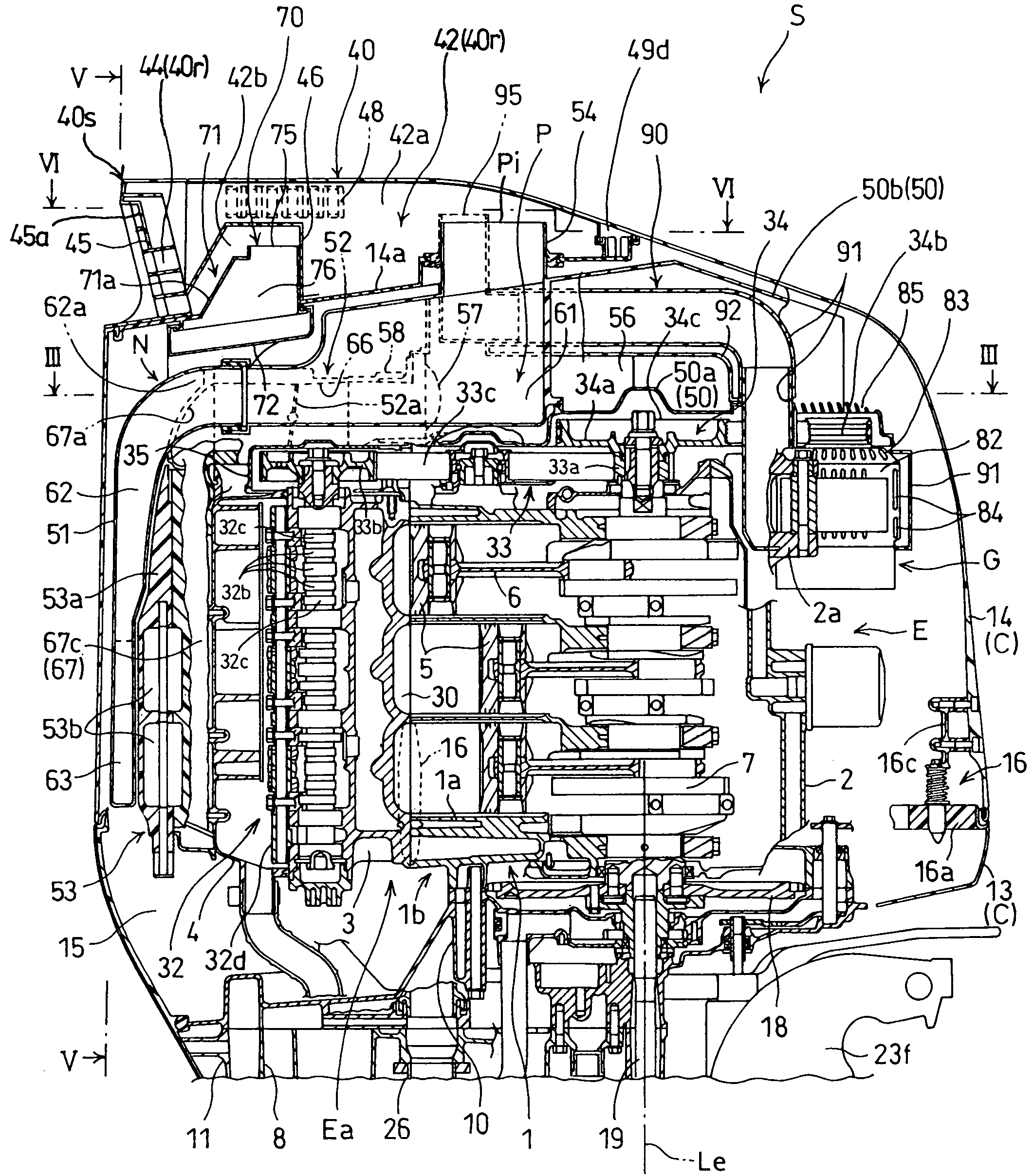
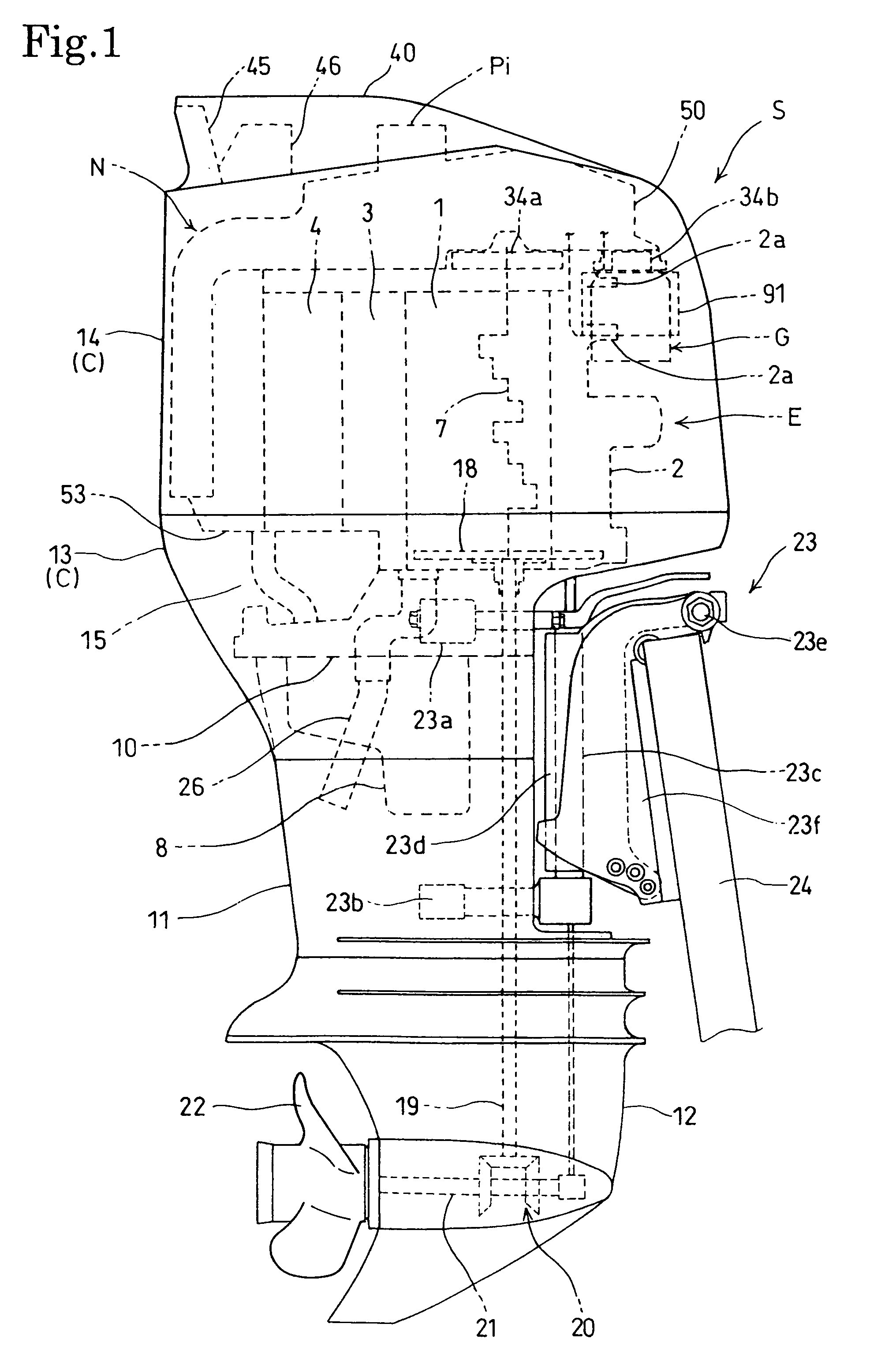
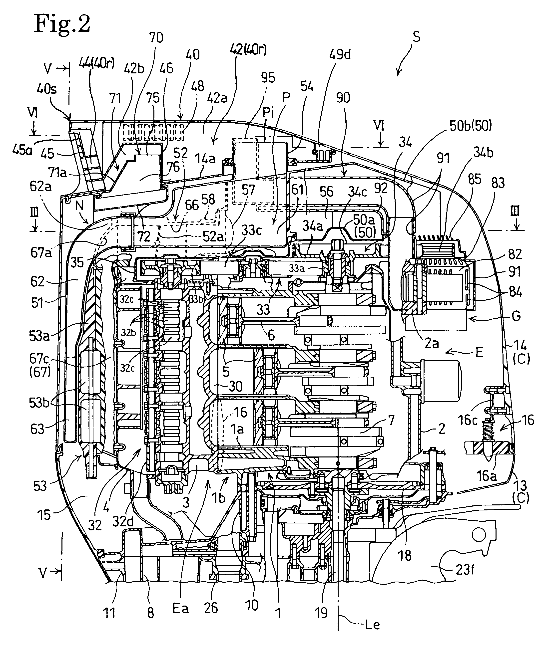
[0029]An outboard motor in a preferred embodiment of the present invention will be described with reference to FIGS. 1 to 8.

[0030]Referring to FIGS. 1 and 2, an outboard motor S, namely, a marine propulsion apparatus as a machine to which the present invention is applied, includes a propulsion unit, namely, a power unit, and a mounting device 23 for holding the propulsion unit on a hull 24. The propulsion unit includes an internal combustion engine E, a propeller unit driven by the internal combustion engine E to generate thrust, an alternator G, cases 10, 11 and 12, and an engine cover C.

[0031]Referring also to FIG. 3, the internal combustion engine E is a vertical, water-cooled multicylinder 4-stroke internal combustion engine provided with a vertical crankshaft 7 disposed with its center axis Le set in a vertical position. In this embodiment, the internal combustion engine E is a V-6 internal combustion engine. The internal combustion engine E has an engine body Ea including a cy...


PUM


Abstract

An internal combustion engine installed in an engine compartment 15 covered with an engine cover C is provided with an intake air passage P. The intake air passage P extends continuously from an intake air inlet Pi to intake air outlets Pe in the engine compartment 15 and has a first down passage 62, a reversing passage 63, an up passage 64 and a second down passage 67c arranged in the order in the flowing direction of combustion air. The combustion air taken through the intake air inlet Pi into the intake air passage P flows down through the first down passage 62, the reversing passage 63 reverses the flowing direction of the combustion air that has flowed down through the first down passage 62 such that the combustion air flows up, flows up through the up passage 64 to a position at a level higher than that of an uppermost intake air outlet Pe. Then, the combustion air flows down through the second down passage 67c and flows through the intake air outlets Pe into combustion chambers 30. Thus, an effect on preventing the flow of water into the combustion chamber 30 of the engine is improved.

Description

BACKGROUND OF THE INVENTION[0001]1. Field of the Invention[0002]The present invention relates to an internal combustion engine installed in an engine compartment covered with an engine cover, and an outboard motor provided with the internal combustion engine. More specifically, the present invention relates to a construction of the intake air passage of an internal combustion engine.[0003]2. Description of the Related Art[0004]There are various known techniques for preventing water from flowing together with the combustion air into the combustion chambers of an internal combustion engine. Particularly, an internal combustion engine included in a marine propulsion apparatus, such as an outboard motor, is required to be compact in construction and excellent in water eliminating function. For instance, a technique applied to an internal combustion engine included in an outboard motor disclosed in Japan Patent No. 2726718 uses a U-shaped intake air passage to prevent water from flowing ...

Claims


Application Information

Patent Timeline
Patent Type & Authority Patents(United States)
IPC IPC(8): B63B35/73
CPCF02M35/10111F02M35/10295F02M35/168F02M35/10354
Inventor IDE, SHINICHIKASAI, KOJIWADA, TETSUIKENO, TETSUROHASEI, SHOJITAKAHASHI, HIROSHI
Owner HONDA MOTOR CO LTD
Why Eureka
Try Eureka